Content .. 1515 1516 1517 1518 ..
Nissan Altima L32. Manual - part 1517
TM-412
< PRECAUTION >
[CVT: RE0F10A]
PRECAUTIONS
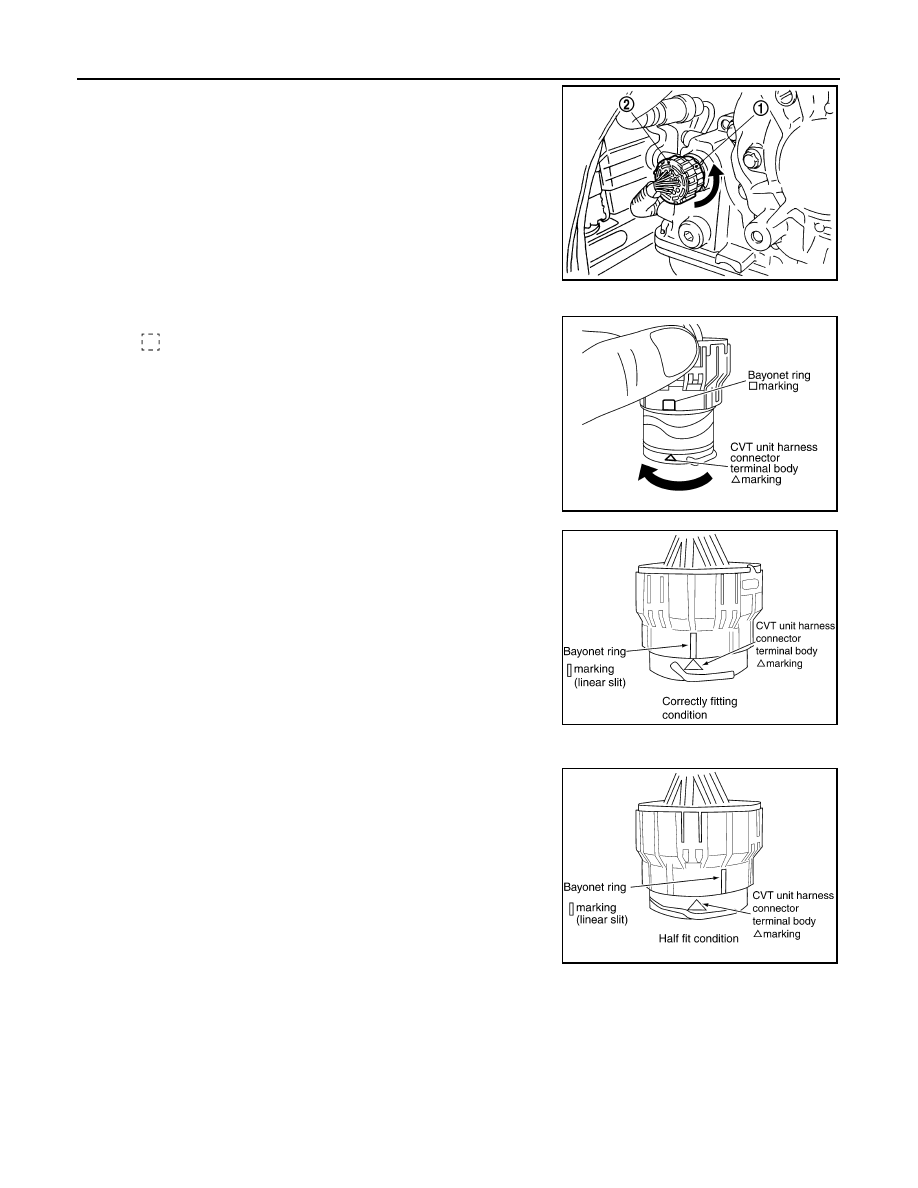
Rotate bayonet ring (1) counterclockwise, pull out CVT unit harness
connector (2) and remove it.
INSTALLATION
1. Align
∆ marking on CVT unit harness connector terminal body
with marking on bayonet ring, insert CVT unit harness con-
nector, and then rotate bayonet ring clockwise.
2. Rotate bayonet ring clockwise until
∆ marking on CVT unit har-
ness connector terminal body is aligned with the slit on bayonet
ring as shown in the figure (correctly fitting condition), install
CVT unit harness connector to CVT unit harness connector ter-
minal body.
CAUTION:
• Securely align
∆ marking on CVT unit harness connector
terminal body with bayonet ring slit. Then, be careful not
to make a half fit condition as shown in the figure.
• Do not mistake the slit of bayonet ring for other dent por-
tion.
Precaution
INFOID:0000000004201987
NOTE:
If any malfunction occurs in the RE0F10A model transaxle, replace the entire transaxle assembly.
SCIA6685J
SCIA2097E
SCIA2098E
SCIA2099E