Nissan Altima L32. Manual - part 147
BR-26
< ON-VEHICLE REPAIR >
VACUUM LINES
VACUUM LINES
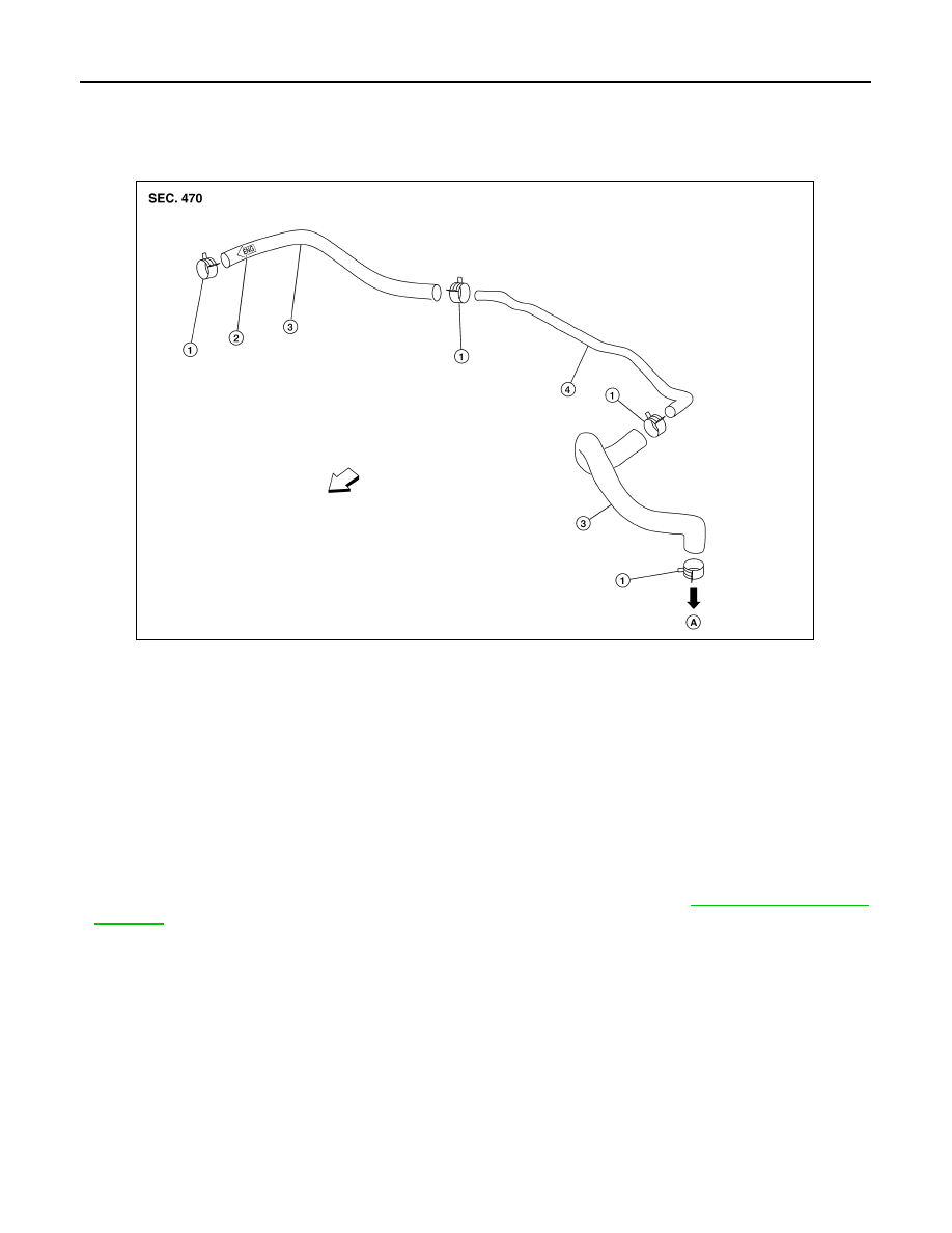
Exploded View
INFOID:0000000004204183
Removal and Installation
INFOID:0000000004204184
REMOVAL
1. Disconnect the vacuum hose from the brake booster.
2. Disconnect the vacuum hose from the engine intake manifold.
3. Remove the vacuum hose.
INSTALLATION
Installation is in the reverse order of removal.
• Inspect the vacuum hose and one-way check valve before installation. Refer to
.
CAUTION:
• Because the vacuum hose contains a one-way check valve, the hose must be installed in the correct
position. Refer to the stamp on the hose to confirm the correct direction for installation. The brake
booster will not operate normally if the hose is installed in the wrong direction.
• Do not use lubricating oil during assembly.
1.
Clamp
2.
Check valve direction stamp
3.
Vacuum hose
4.
Vacuum piping
A. To brake booster
⇐ Front
WFIA0421E