Nissan Altima L32. Manual - part 1453


  Index      Nissan     Nissan Altima L32 (2007-2009 year) - Service and Repair Manual


Search            


Content   ..  1451  1452  1453  1454   ..


Nissan Altima L32. Manual - part 1453


TM-156

< COMPONENT DIAGNOSIS >

[CVT: RE0F09B]

P0778 PRESSURE CONTROL SOLENOID B ELECTRICAL (SEC PRESSURE 

SOLENOID VALVE)

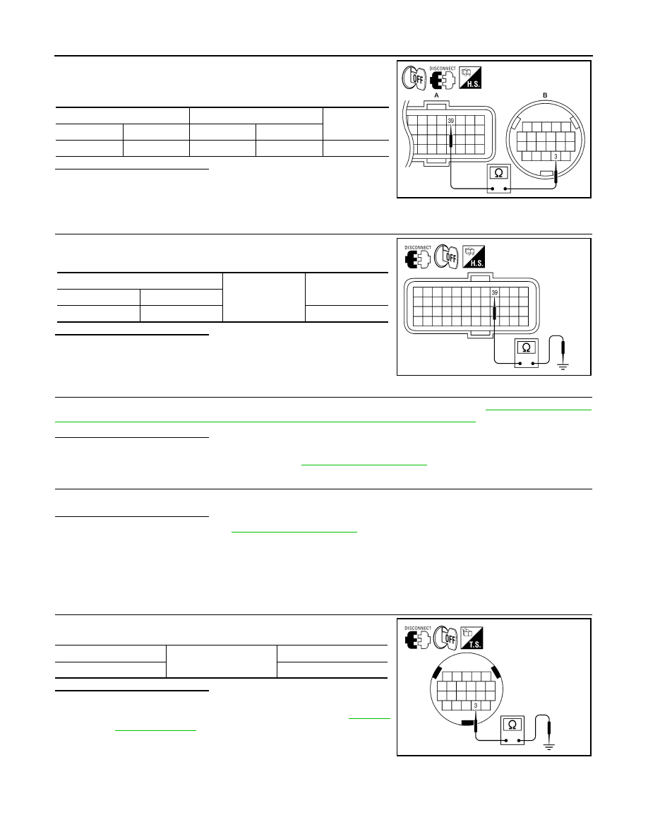
1. Disconnect CVT unit harness connector.

2. Check continuity between TCM harness connector F16 (A) ter-

minal 39 and CVT unit harness connector F46 (B) terminal 3.

Is the inspection result normal?

YES

>> GO TO 3.

NO

>> Repair or replace damaged parts.

3.

CHECK HARNESS BETWEEN TCM AND PRESSURE CONTROL SOLENOID VALVE B (SECONDARY

PRESSURE SOLENOID VALVE) (PART 2)
Check continuity between TCM harness connector F16 terminal 39

and ground.

Is the inspection result normal?

YES

>> GO TO 4.

NO

>> Repair or replace damaged parts.

4.

CHECK PRESSURE CONTROL SOLENOID VALVE B (SECONDARY PRESSURE SOLENOID VALVE)

Check pressure control solenoid valve B (secondary pressure solenoid valve). Refer to 

TM-156, "Component

Inspection [Pressure Control Solenoid Valve B (Secondary Pressure Solenoid Valve)]"

.

Is the inspection result normal?

YES 

>> GO TO 5.

NO

>> Replace transaxle assembly. Refer to 

TM-259, "Exploded View"

.

5.

DETECT MALFUNCTIONING ITEMS

Check TCM connector pin terminals for damage or loose connection with harness connector.
Is the inspection result normal?

YES

>> Replace TCM. Refer to 

TM-254, "Exploded View"

.

NO

>> Repair or replace damaged parts.

Component Inspection [Pressure Control Solenoid Valve B (Secondary Pressure So-
lenoid Valve)]

INFOID:0000000004201719

1.

CHECK PRESSURE CONTROL SOLENOID VALVE B (SECONDARY PRESSURE SOLENOID VALVE)

Check resistance between CVT unit terminal 3 and ground.

Is the inspection result normal?

YES

>> INSPECTION END

NO

>> Replace transaxle assembly. Refer to 

TM-259,

"Exploded View"

.

TCM harness connector

CVT unit harness connector

Continuity

Connector

Terminal

Connector

Terminal

F16 (A)

39

F46 (B)

3

Existed

AWDIA0125ZZ

TCM harness connector

Ground

Continuity

Connector

Terminal

F16

39

Not existed

AWDIA0124ZZ

CVT unit terminal

Ground

Resistance (Approx.)

3

3.0 – 9.0 

AWDIA0123ZZ

P0826 MANUAL MODE SWITCH

TM-157

< COMPONENT DIAGNOSIS >

[CVT: RE0F09B]

C

E

F

G

H

I

J

K

L

M

A

B

TM

N

O

P

P0826 MANUAL MODE SWITCH

Description

INFOID:0000000004201720

Manual mode switch is installed in CVT control device. The manual mode switch sends shift up and shift down

switch signals to TCM.

TCM sends the switch signals to combination meter via CAN communication line. Then manual mode switch

position is indicated on the CVT position indicator.

DTC Logic

INFOID:0000000004201721

DTC DETECTION LOGIC

DTC CONFIRMATION PROCEDURE

CAUTION:

Always drive vehicle at a safe speed.

NOTE:

If “DTC CONFIRMATION PROCEDURE” has been previously performed, always turn ignition switch OFF.

Then wait at least 10 seconds before performing the next test.

1.

CHECK DTC DETECTION

With CONSULT-III

1. Turn ignition switch ON.

2. Select “DATA MONITOR”.

3. Drive vehicle and maintain the following conditions for at least 2 consecutive seconds.

Is “P0826 MANUAL MODE SWITCH” detected?

YES

>> Go to 

TM-157, "Diagnosis Procedure"

.

NO

>> Check intermittent incident. Refer to 

GI-42, "Intermittent Incident"

.

Diagnosis Procedure

INFOID:0000000004201722

1.

CHECK MANUAL MODE SWITCH SIGNALS

With CONSULT-III

1. Turn ignition switch ON.

2. Select “DATA MONITOR”.

3. Check the ON/OFF operations of each monitor item.

DTC

Item

(CONSULT-III screen term)

Malfunction is detected when...

Possible cause

P0826

MANUAL MODE SWITCH

When an impossible pattern of switch sig-
nals is detected, a malfunction is detected.

• Harness or connectors
- (These switches circuit is open or short-

ed.)

- (TCM, and combination meter circuit are 

open or shorted.)

- (CAN communication line is open or 

shorted.)

• Manual mode select switch (Built into con-

trol device)

• Manual mode position select switch (Built 

into control device)

MMODE

: On

Item name

Condition

Display value

MMODE

Manual shift gate position (neutral)

On

Other than the above

Off

NONMMODE

Manual shift gate position (neutral, +side, 

−side)

Off

Other than the above

On

TM-158

< COMPONENT DIAGNOSIS >

[CVT: RE0F09B]

P0826 MANUAL MODE SWITCH

Without CONSULT-III

Drive vehicle in the manual mode, and confirm that the actual gear position and the meter's indication of the

position mutually coincide when the selector lever is shifted to the “+ (up)” or “

− (down)” side (1st ⇔ 6th gear).

Is the inspection result normal?

YES

>> GO TO 7.

NO

>> GO TO 2.

2.

CHECK HARNESS BETWEEN CVT DEVICE AND COMBINATION METER (PART 1)

1. Turn ignition switch OFF.

2. Disconnect CVT device harness connector and combination

meter harness connector.

3. Check continuity between CVT device harness connector M23

(A) terminal 1, 2, 3 and 5 and combination meter harness con-

nector M24 (B) terminal 40, 38, 39 and 37.

Is the inspection result normal?

YES

>> GO TO 3.

NO

>> Repair or replace damaged parts.

3.

CHECK HARNESS BETWEEN CVT DEVICE AND COMBINATION METER (PART 2)

Check continuity between CVT device harness connector M23 termi-

nal 1, 2, 3, and 5 and ground.

Is the inspection result normal?

YES

>> GO TO 4.

NO

>> Repair or replace damaged parts.

4.

CHECK GROUND CIRCUIT (PART 1)

UPLVR

Selector lever: + side

On

Other than the above

Off

DOWNLVR

Selector lever: 

− side

On

Other than the above

Off

Item name

Condition

Display value

CVT device harness connector

Combination meter harness 

connector

Continuity

Connector

Terminal

Connector

Terminal

M23 (A)

1

M24 (B)

40

Existed

2

38

3

39

5

37

AWDIA0126ZZ

CVT device harness connector

Ground

Continuity

Connector

Terminal

M23

1

Not existed

2

3

5

AWDIA0127ZZ

P0826 MANUAL MODE SWITCH

TM-159

< COMPONENT DIAGNOSIS >

[CVT: RE0F09B]

C

E

F

G

H

I

J

K

L

M

A

B

TM

N

O

P

Check continuity between CVT device harness connector M23 termi-

nal 4 and ground.

Is the inspection result normal?

YES

>> GO TO 5.

NO

>> Repair or replace damaged parts.

5.

CHECK GROUND CIRCUIT (PART 2)

1. Turn ignition switch ON.

2. Check voltage between CVT device harness connector M23 ter-

minal 4 and ground.

Is the inspection result normal?

YES

>> GO TO 6.

NO

>> Repair or replace damaged parts.

6.

CHECK MANUAL MODE SWITCH

Check manual mode switch. Refer to 

TM-159, "Component Inspection (Manual Mode Switch)"

.

Is the inspection result normal?

YES

>> GO TO 7.

NO

>> Repair or replace damaged parts.

7.

DETECT MALFUNCTIONING ITEMS

Check TCM connector pin terminals for damage or loose connection with harness connector.
Is the inspection result normal?

YES

>> Replace TCM. Refer to 

TM-254, "Exploded View"

.

NO

>> Repair or replace damaged parts.

Component Inspection (Manual Mode Switch)

INFOID:0000000004201723

1.

CHECK MANUAL MODE SWITCH

Check continuity between CVT device terminals.

Is the inspection result normal?

YES

>> INSPECTION END

NO

>> Repair or replace damaged parts.

CVT device harness connector

Ground

Continuity 

Connector

Terminal

M23

4

Existed

AWDIA0128ZZ

CVT device harness connector

Ground

Voltage (Approx.) 

Connector

Terminal

M23

4

0 V

AWDIA0129ZZ

CVT device terminals

Condition

Continuity

5

4

Manual shift gate position (neutral)

Not existed

Other than the above

Existed

1

4

Manual shift gate position (neutral)

Existed

Other than the above

Not existed

3

4

Selector lever: UP (+ side)

Existed

Other than the above

Not existed

2

4

Selector lever: DOWN (

− side)

Existed

Other than the above

Not existed

AWDIA0130ZZ


Content   ..  1451  1452  1453  1454   ..