Nissan Altima L32. Manual - part 1440


  Index      Nissan     Nissan Altima L32 (2007-2009 year) - Service and Repair Manual


Search            


Content   ..  1438  1439  1440  1441   ..


Nissan Altima L32. Manual - part 1440


TM-104

< FUNCTION DIAGNOSIS >

[CVT: RE0F09B]

CONTROL SYSTEM

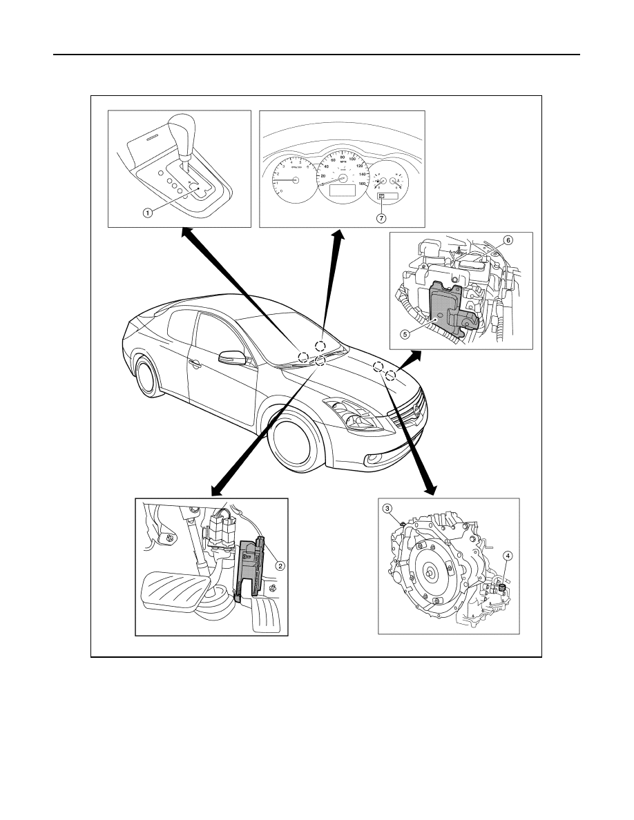
Component Parts Location - Coupe

INFOID:0000000004201644

1.

Control device assembly (Manual 
mode select switch and manual 
mode position select switch)

2.

Accelerator pedal position (APP) 
sensor

3.

Secondary speed sensor

4.

CVT unit harness connector

5.

TCM

6.

Battery

7.

Shift position indicator
Manual mode indicator

AWDIA0166ZZ

CONTROL SYSTEM

TM-105

< FUNCTION DIAGNOSIS >

[CVT: RE0F09B]

C

E

F

G

H

I

J

K

L

M

A

B

TM

N

O

P

Component Parts Location - Sedan

INFOID:0000000004201645

1.

Control device assembly (Manual 
mode select switch and manual 
mode position select switch)

2.

Accelerator pedal position (APP) 
sensor

3.

Secondary speed sensor

4.

CVT unit harness connector

5.

TCM

6.

Battery

7.

Shift position indicator
Manual mode indicator

AWIIA0001ZZ

TM-106

< FUNCTION DIAGNOSIS >

[CVT: RE0F09B]

CONTROL SYSTEM

Component Description

INFOID:0000000004201646

TRANSAXLE ASSEMBLY

EXCEPT TRANSAXLE ASSEMBLY

Name

Function

PNP switch

TM-129

CVT fluid temperature sensor

TM-132

Primary speed sensor

TM-135

Secondary speed sensor

TM-138

Primary pressure sensor

TM-138

Secondary pressure sensor

TM-160

Step motor

TM-184

TCC solenoid valve

TM-144

Lock-up select solenoid valve

TM-181

Line pressure solenoid valve

TM-148

Secondary pressure solenoid valve

TM-155

Name

Function

TCM

Optimally controls continuously variable transmission system by judging driving condi-
tions based on signals from each sensor.

Stop lamp switch

TM-126

LOCK-UP AND SELECT CONTROL SYSTEM

TM-107

< FUNCTION DIAGNOSIS >

[CVT: RE0F09B]

C

E

F

G

H

I

J

K

L

M

A

B

TM

N

O

P

LOCK-UP AND SELECT CONTROL SYSTEM

System Diagram

INFOID:0000000004201647

System Description

INFOID:0000000004201648

• The torque converter clutch piston in the torque converter is engaged to eliminate torque converter slip to

increase power transmission efficiency.

• The torque converter clutch control valve operation is controlled by the torque converter clutch solenoid

valve, which is controlled by a signal from TCM. The torque converter clutch control valve engages or

releases the torque converter clutch piston.

• When shifting between “N” (“P”) 

⇔ “D” (“R”), torque converter clutch solenoid controls engagement power of

forward clutch and reverse brake.

• The lock-up applied gear range was expanded by locking up the

torque converter at a lower vehicle speed than conventional CVT

models.

TORQUE CONVERTER CLUTCH AND SELECT CONTROL VALVE CONTROL 

Lock-up Released 

In the lock-up released state, the torque converter clutch control valve is set into the unlocked state by the

torque converter clutch solenoid and the lock-up apply pressure is drained.

In this way, the torque converter clutch piston is not coupled.

Lock-up Applied

In the lock-up applied state, the torque converter clutch control valve is set into the locked state by the torque

converter clutch solenoid and lock-up apply pressure is generated.

In this way, the torque converter clutch piston is pressed and coupled.

Select Control

When shifting between “N” (“P”) 

⇔ “D” (“R”), optimize the operating pressure on the basis of the throttle posi-

tion, the engine speed, and the secondary pulley (output) revolution speed to lessen the shift shock.

SCIA2374E

SCIA1958E


Content   ..  1438  1439  1440  1441   ..