Content .. 1407 1408 1409 1410 ..
Nissan Altima L32. Manual - part 1409
STR-32
< FUNCTION DIAGNOSIS >
[VQ35DE]
STARTING SYSTEM
FUNCTION DIAGNOSIS
STARTING SYSTEM
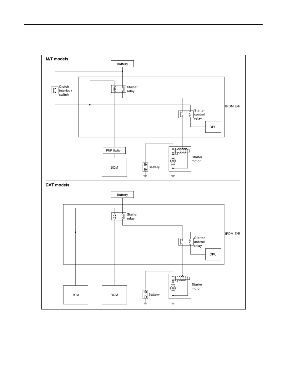
System Diagram
INFOID:0000000004205246
System Description
INFOID:0000000004205247
The starter motor plunger closes and provides a closed circuit between the battery and the starter motor. The
starter motor is grounded to the cylinder block. With power and ground supplied, the starter motor operates.
AWBIA0742GB