Content .. 1274 1275 1276 1277 ..
Nissan Altima L32. Manual - part 1276
SEC-254
< COMPONENT DIAGNOSIS >
[SEDAN WITH INTELLIGENT KEY]
B210F PNP/CLUTCH INTERLOCK SWITCH
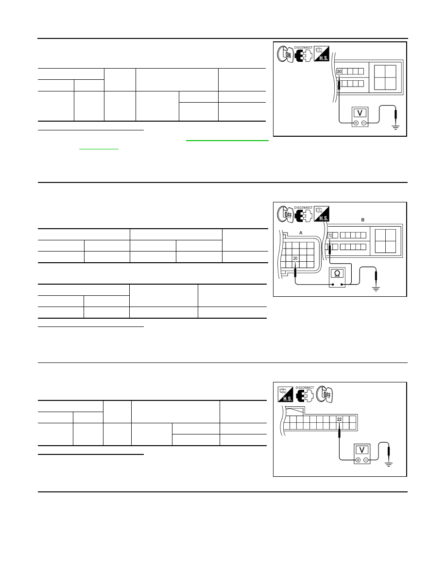
4. Check voltage between IPDM E/R harness connector and
ground under following condition.
Is the inspection result normal?
YES
NO
>> (VQ35DE) GO TO 4
NO
>> (QR25DE) GO TO 10
4.
CHECK PNP SWITCH CIRCUIT
1. Turn ignition switch OFF.
2. Disconnect TCM harness connector.
3. Check continuity between IPDM E/R harness connector and
TCM harness connector.
4. Check continuity between TCM harness connector and ground.
Is the inspection result normal?
YES
>> GO TO 13
NO
>> Repair harness or connector.
5.
CHECK CLUTCH INTERLOCK SWITCH INPUT SIGNAL (BCM)
1. Turn ignition switch OFF.
2. Disconnect BCM harness connector.
3. Check voltage between BCM harness connector and ground.
Is the inspection result normal?
YES
>> GO TO 6
NO
>> GO TO 7
6.
CHECK CLUTCH INTERLOCK SWITCH INPUT SIGNAL
1. Turn ignition switch OFF.
2. Disconnect IPDM E/R harness connector.
3. Turn ignition switch ON.
IPDM E/R
Ground
Condition
Voltage (V)
Connector
Terminal
E18
30
Ground
CVT selector
lever
P or N
0
Other than
above
Battery voltage
ALKIA1308ZZ
TCM
IPDM E/R
Continuity
Connector
Terminal
Connector
Terminal
A: F16
20
B: E18
72
Yes
TCM
Ground
Continuity
Connector
Terminal
A: F16
20
Ground
No
ALKIA1309ZZ
BCM
Ground
Condition
Voltage (V)
Connector Terminal
M18
22
Ground
Clutch pedal
Not depressed
0
Depressed
Battery voltage
ALKIA1310ZZ