Nissan Altima L32. Manual - part 1239


  Index      Nissan     Nissan Altima L32 (2007-2009 year) - Service and Repair Manual


Search            


Content   ..  1237  1238  1239  1240   ..


Nissan Altima L32. Manual - part 1239


SEC-106

< COMPONENT DIAGNOSIS >

[COUPE]

B2617 STARTER RELAY CIRCUIT

Is the measurement value within the specification.

YES

>> GO TO 3

NO

>> GO TO 2

2.

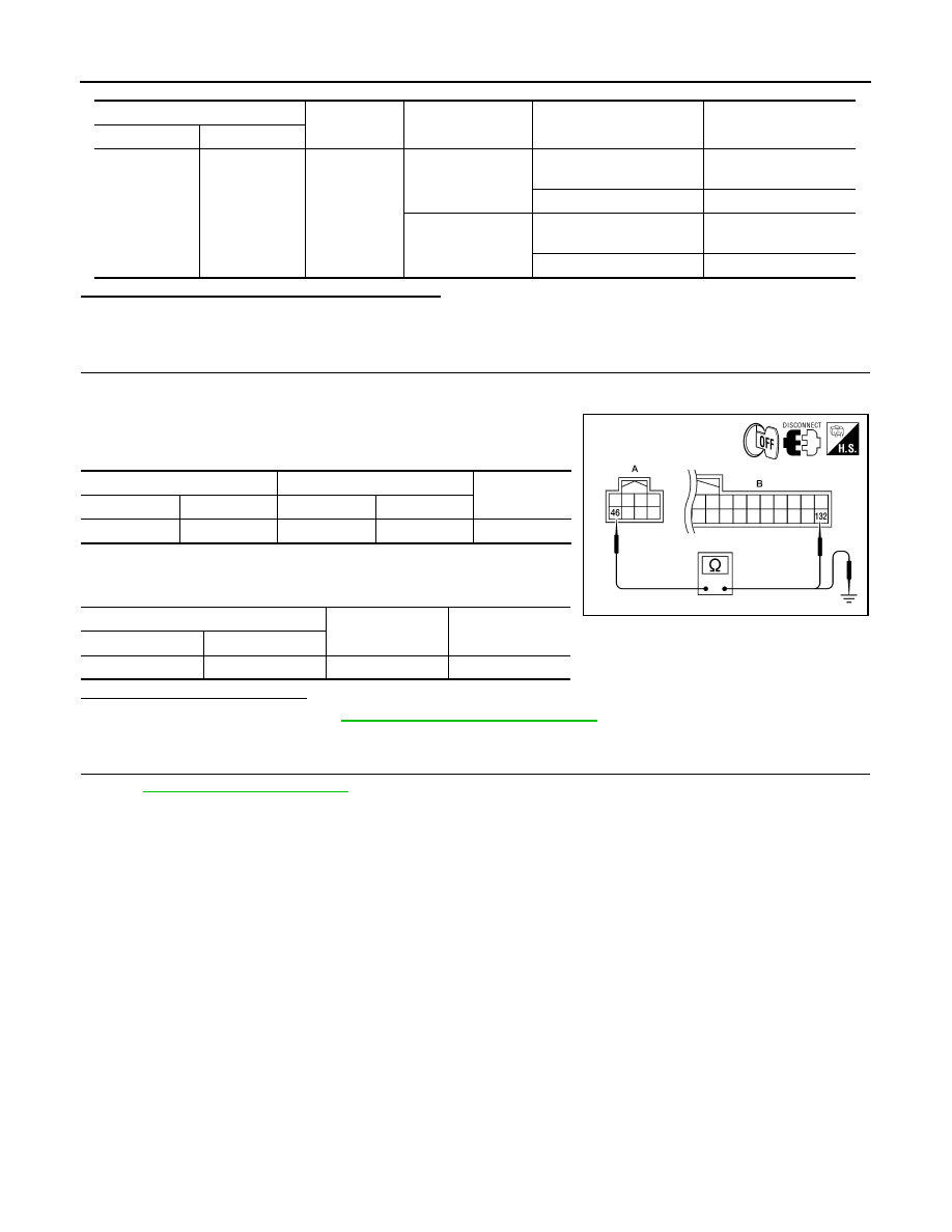
CHECK STARTER RELAY CIRCUIT

1. Turn ignition switch OFF.

2. Disconnect BCM harness connector and IPDM E/R harness connector.

3. Check continuity between IPDM E/R harness connector and

BCM harness connector.

4. Check continuity between IPDM E/R harness connector and

ground.

Is the inspection result normal?

YES

>> Replace BCM. Refer to 

BCS-96, "Removal and Installation"

.

NO

>> Repair harness or connector.

3.

CHECK INTERMITTENT INCIDENT

Refer to 

GI-42, "Intermittent Incident"

.

>> Inspection End.

BCM

Ground

Transmission type

Condition

Voltage (V)

Connector

Terminal

M21

132

Ground

CVT: Select lever in 
Park

Ignition switch cranking or 

request to start

Battery voltage

Other than above

0

M/T: Clutch pedal 
depressed

Ignition switch cranking or 

request to start

Battery voltage

Other than above

0

IPDM E/R

BCM

Continuity

Connector

Terminal

Connector

Terminal

A: E17

46

B: M21

132

Yes

IPDM E/R

Ground

Continuity

Connector

Terminal

A: E17

46

Ground

No

ALKIA1318ZZ

B2619 BCM

SEC-107

< COMPONENT DIAGNOSIS >

[COUPE]

C

D

E

F

G

H

I

J

L

M

A

B

SEC

N

O

P

B2619 BCM

Description

INFOID:0000000004206092

BCM requests IPDM E/R to supply power to steering lock unit. After receiving the power, the steering lock unit

transmits an ON signal to BCM.

DTC Logic

INFOID:0000000004206093

DTC DETECTION LOGIC

DTC CONFIRMATION PROCEDURE

1.

PERFORM DTC CONFIRMATION PROCEDURE

1. Press the push-button ignition switch under the following conditions and wait for at least 1 second.

-

CVT selector lever is in the P position

-

Do not depress brake pedal

2. Check “Self diagnostic result” with CONSULT-III.
Is DTC detected?

YES

>> Refer to 

SEC-107, "Diagnosis Procedure"

.

NO

>> Inspection End.

Diagnosis Procedure

INFOID:0000000004206094

1.

INSPECTION START

1. Turn ignition switch ON.

2. Check “Self diagnostic result” with CONSULT-III.

3. Touch “ERASE”.

4. Perform DTC Confirmation Procedure.

See 

SEC-107, "DTC Logic"

.

Is the DTC B2619 displayed again?

YES

>> Replace BCM. Refer to 

BCS-96, "Removal and Installation"

.

NO

>> Inspection End.

DTC No.

Trouble diagnosis 

name

DTC detecting condition

Possible cause

B2619

BCM

BCM detects a mismatch between the power sup-
plied to the steering lock unit and the feedback for 
one second or more.

• BCM

SEC-108

< COMPONENT DIAGNOSIS >

[COUPE]

B261A PUSH-BUTTON IGNITION SWITCH

B261A PUSH-BUTTON IGNITION SWITCH

Description

INFOID:0000000004206095

IPDM E/R transmits the push-button ignition switch status via CAN communication to BCM. BCM receives

push-button ignition switch status by hardwire input. BCM compares the 2 signals for mismatch.

DTC Logic

INFOID:0000000004206096

DTC DETECTION LOGIC

NOTE:

• If DTC B261A is displayed with DTC U1000, first perform the trouble diagnosis for DTC U1000. Refer to

SEC-36, "DTC Logic"

.

• If DTC B261A is displayed with DTC U1010, first perform the trouble diagnosis for DTC U1010. Refer to

SEC-37, "DTC Logic"

.

DTC CONFIRMATION PROCEDURE

1.

PERFORM DTC CONFIRMATION PROCEDURE

1. Press the push-button ignition switch under the following conditions and wait for at least 1 second.

-

CVT selector lever is in the P position

-

Do not depress brake pedal.

2. Check “Self diagnostic result” with CONSULT-III.
Is DTC detected?

YES

>> Refer to 

SEC-108, "Diagnosis Procedure"

.

NO

>> Inspection End.

Diagnosis Procedure

INFOID:0000000004206097

1.

CHECK PUSH-BUTTON IGNITION SWITCH OUTPUT SIGNAL 1

1. Turn ignition switch OFF.

2. Disconnect push-button ignition switch harness connector and IPDM E/R harness connector.

3. Check voltage between push-button ignition switch harness con-

nector and ground.

Is the inspection result normal?

YES

>> GO TO 4

NO

>> GO TO 2

2.

CHECK PUSH-BUTTON IGNITION SWITCH CIRCUIT

1. Disconnect BCM harness connector.

DTC No.

Trouble diagnosis 

name

DTC detecting condition

Possible cause

B261A

PUSH-BUTTON 
IGNITION 
SWITCH

BCM detects the mismatch between the following for 1 
second or more
• Push-button ignition switch status
• Push-button ignition switch status from IPDM E/R (CAN)

• Harness or connectors

(Push-button ignition switch circuit is 
open or shorted)

• Between BCM and push-button igni-

tion switch

• Between IPDM E/R and push-button 

ignition switch

Push-button ignition switch

Ground

Voltage (V)

Connector

Terminal

M38

4

Ground

Battery voltage

ALKIA1350ZZ

B261A PUSH-BUTTON IGNITION SWITCH

SEC-109

< COMPONENT DIAGNOSIS >

[COUPE]

C

D

E

F

G

H

I

J

L

M

A

B

SEC

N

O

P

2. Check continuity between push-button ignition switch harness

connector M38 (A) terminal 4 and BCM harness connector M19

(B) terminal 77.

3. Check continuity between push-button ignition switch harness

connector M38 (A) terminal 4 and ground.

Is the inspection result normal?

YES

>> GO TO 3

NO

>> Repair harness or connector.

3.

CHECK PUSH-BUTTON IGNITION SWITCH

1. Disconnect IPDM E/R harness connector.

2. Check continuity between push-button ignition switch harness

connector M38 (A) terminal 4 and IPDM E/R harness connector

E18 (B) terminal 28.

3. Check continuity between push-button ignition switch harness

connector and ground.

Is the inspection result normal?

YES

>> GO TO 4

NO

>> Repair harness or connector.

4.

CHECK INTERMITTENT INCIDENT

Refer to 

GI-42, "Intermittent Incident"

.

>> Inspection End.

Push-button ignition switch

BCM

Continuity

Connector

Terminal

Connector

Terminal

A: M38

4

B: M19

77

Yes

Push-button ignition switch

Ground

Continuity

Connector

Terminal

A: M38

4

Ground

No

ALKIA0460ZZ

Push-button ignition switch

IPDM E/R

Continuity

Connector

Terminal

Connector

Terminal

A: M38

4

B: E18

28

Yes

Push-button ignition switch

Ground

Continuity

Connector

Terminal

A: M38

4

Ground

No

ALKIA0461ZZ


Content   ..  1237  1238  1239  1240   ..