Nissan Altima L32. Manual - part 83
AV-324
< COMPONENT DIAGNOSIS >
[BOSE AUDIO WITH NAVIGATION]
POWER SUPPLY AND GROUND CIRCUIT (SEDAN)
Are the fuses OK?
YES
>> GO TO 2
NO
>> Be sure to eliminate cause of malfunction before installing new fuse.
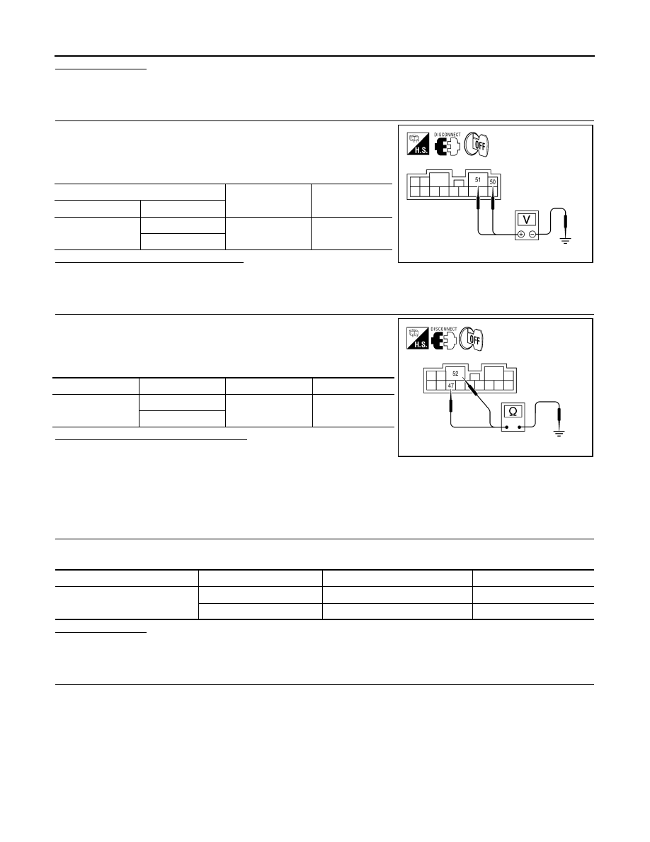
2.
CHECK POWER SUPPLY CIRCUIT
1. Turn ignition switch OFF.
2. Disconnect BOSE speaker amp connector.
3. Check voltage between BOSE speaker amp harness connector
and ground.
Are the voltage readings as specified?
YES
>> GO TO 3
NO
>> Check harness between BOSE speaker amp. and fuse.
3.
CHECK GROUND CIRCUIT
1. Turn ignition switch OFF.
2. Disconnect BOSE speaker amp connector.
3. Check continuity between BOSE speaker amp harness connec-
tor and ground.
Are continuity test results as specified?
YES
>> Inspection End.
NO
>> Repair harness or connector.
CD CHANGER
CD CHANGER : Diagnosis Procedure
INFOID:0000000004206636
1.
CHECK FUSE
Check that the following fuses of the CD changer are not blown.
Are the fuses OK?
YES
>> GO TO 2
NO
>> Be sure to eliminate cause of malfunction before installing new fuse.
2.
CHECK POWER SUPPLY CIRCUIT
(+)
(-)
Voltage (approx.)
Connector
Terminal
B122
50
Ground
Battery voltage
51
ALNIA0128ZZ
Connector
Terminal
—
Continuity
B122
47
Ground
Yes
52
ALNIA0129ZZ
Unit
Terminals
Signal name
Fuse No.
CD changer
12
Battery power
24
16
Ignition switch ACC or ON
19