Nissan Titan. Manual - part 316
EM-68
< REMOVAL AND INSTALLATION >
CAMSHAFT
• Measure the diameter of the valve lifter.
Valve Lifter Hole Diameter
• Measure the diameter of the valve lifter hole of the cylinder head,
using suitable tool.
Calculation of Valve Lifter Clearance
(Valve lifter clearance) = (valve lifter hole diameter) – (valve lifter
diameter)
• If the measurement is not within specification, referring to each
specification of the valve lifter diameter and hole diameter, replace
either or both the valve lifter and cylinder head.
INSTALLATION
1. Install the valve lifters if removed.
• Install removed parts in their original locations.
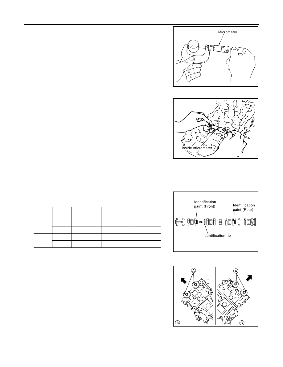
2. Install the camshafts. Use the table below for identification of the
(RH) and (LH), and intake and exhaust.
• Install so that the (RH) bank (B) dowel pins (A) and (LH) bank
(C) dowel pins (A) at the front of the camshaft face are in the
direction shown.
Standard
: 33.977 - 33.987 mm (1.3377 - 1.3381 in)
JEM798G
Standard
: 34.000 - 34.016 mm (1.3386 - 1.3392 in)
Standard
: 0.013 - 0.039 mm (0.0005 - 0.0015 in)
PBIC0043E
Bank
INT EXH
Identification
paint (front)
Identification
paint (rear)
Identification
rib
(RH)
INT
Pink
—
Yes
EXH
—
Orange
Yes
(LH)
INT
Pink
—
No
EXH
—
Orange
No
KBIA2523E
WBIA0708E