Nissan Titan. Manual - part 288
ASCD BRAKE SWITCH
EC-453
< DTC/CIRCUIT DIAGNOSIS >
[VK56DE]
C
D
E
F
G
H
I
J
K
L
M
A
EC
N
P
O
OK or NG
OK
>> INSPECTION END
NG
>> GO TO 7.
3.
CHECK ASCD BRAKE SWITCH POWER SUPPLY CIRCUIT
1. Turn ignition switch OFF.
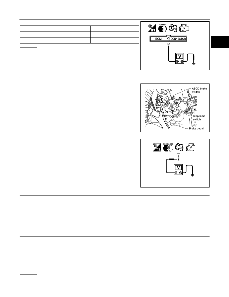
2. Disconnect ASCD brake switch harness connector.
3. Turn ignition switch ON.
4. Check voltage between ASCD brake switch terminal 1 and
ground with CONSULT or tester.
OK or NG
OK
>> GO TO 5.
NG
>> GO TO 4.
4.
DETECT MALFUNCTIONING PART
Check the following.
• Harness connectors M31, E152
• Fuse block (J/B) connector M4
• 10A fuse
• Harness for open or short between ASCD brake switch and fuse
>> Repair open circuit or short to ground or short to power in harness or connectors.
5.
CHECK ASCD BRAKE SWITCH INPUT SIGNAL CIRCUIT FOR OPEN AND SHORT
1. Turn ignition switch OFF.
2. Disconnect ECM harness connector.
3. Check harness continuity between ECM terminal 108 and ASCD brake switch terminal 2.
Refer to Wiring Diagram.
4. Also check harness for short to ground and short to power.
OK or NG
OK
>> GO TO 6.
NG
>> Repair open circuit or short to ground or short to power in harness or connectors.
CONDITION
VOLTAGE
Brake pedal: Fully released
Approximately 0V
Brake pedal: Slightly depressed
Battery voltage
PBIB1537E
BBIA0373E
Voltage: Battery voltage
PBIB0857E
Continuity should exist.