Nissan Quest E52. Manual - part 817
INSTRUMENT PANEL ASSEMBLY
IP-17
< REMOVAL AND INSTALLATION >
C
D
E
F
G
H
I
K
L
M
A
B
IP
N
O
P
i.
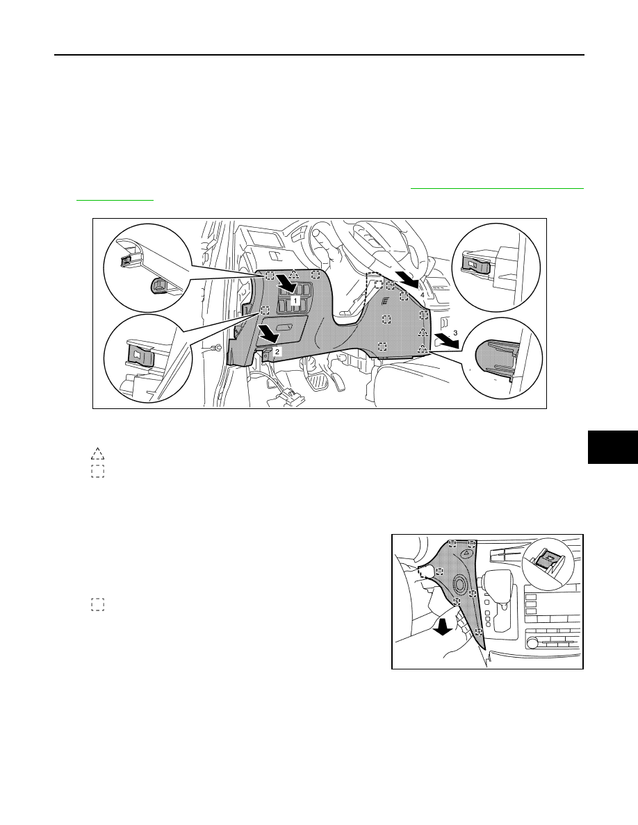
Remove clips (A).
ii.
Pull back instrument lower cover center (1), and then disengage pawl and metal clips.
iii.
Disconnect harness connector and remove harness clip.
b.
With NAVI
i.
Remove clips (A).
ii.
Pull back instrument lower cover center (2), and then disengage metal clips.
iii.
Disconnect harness connector and remove harness clip.
10. Remove instrument lower panel LH.
a.
Remove hood opener and fuel lid opener lever fixing bolts. Refer to
b.
Pull back instrument lower panel LH, and then disengage pawls and metal clips.
CAUTION:
Never pull instrument lower panel LH forcefully.
c.
Release data link connector (pawls) then remove it from instrument lower panel LH.
d.
Disconnect harness connectors, aspirator duct and remove harness clip.
11. Remove instrument finisher A.
a.
Pull back instrument finisher A, and then disengage metal clips.
b.
Disconnect harness connectors.
CAUTION:
Never pull instrument finisher A forcefully.
12. Remove instrument finisher B.
: Pawl
: Metal clip
JMJIA6136ZZ
: Metal clip
JMJIA6137ZZ