Nissan Quest E52. Manual - part 591
CYLINDER BLOCK
EM-113
< UNIT DISASSEMBLY AND ASSEMBLY >
[VQ35DE]
C
D
E
F
G
H
I
J
K
L
M
A
EM
N
P
O
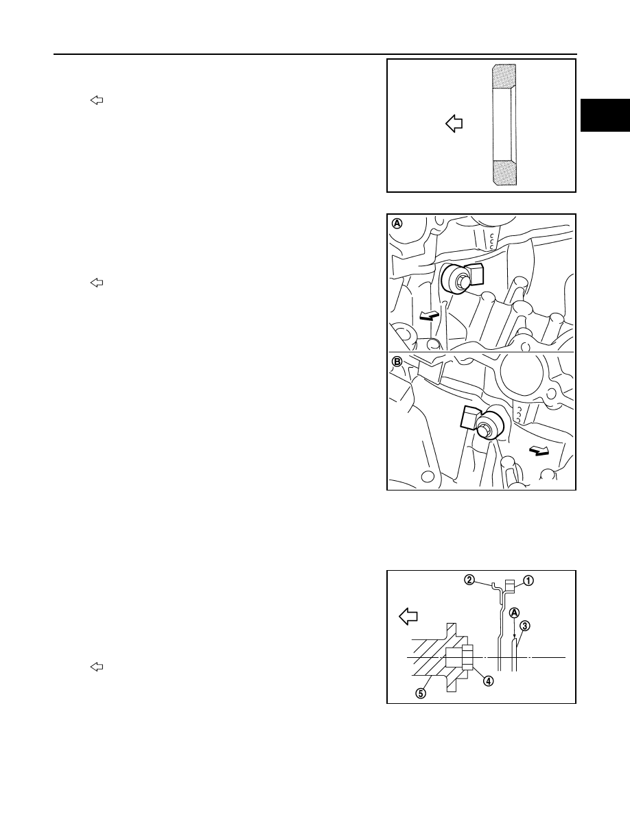
• Press-fit pilot converter with its chamfer facing crankshaft as
shown in the figure.
18. Install knock sensors.
• Install knock sensor so that connector faces the rear of the
engine.
• After installing knock sensor, connect harness connector, and
lay it out to rear of engine.
CAUTION:
• Never tighten mounting bolts while holding connector.
• If any impact by dropping is applied to knock sensor,
replace it with new one.
NOTE:
• Check that there is no foreign material on the cylinder block
mating surface and the back surface of knock sensor.
• Check that knock sensor does not interfere with other parts.
19. Note the following, assemble in the reverse order of disassembly after this step.
Drive plate
• When installing drive plate to crankshaft, be sure to correctly align crankshaft side dowel pin and drive
plate side dowel pin hole.
- If these are not aligned correctly, engine runs roughly and “MIL” turns on.
• Install drive plate (2) and reinforcement plate (3) as shown in
the figure.
• Holding ring gear with the pulley holder (commercial service
tool).
• Tighten mounting bolts crosswise over several times.
Inspection
INFOID:0000000009652800
CRANKSHAFT END PLAY
: Crankshaft side
JPBIA0210ZZ
A
: Bank 1
B
: Bank 2
: Engine front
JPBIA0211ZZ
1
: Ring gear
4
: Pilot converter
5
: Crankshaft
A
: Rounded
: Engine front
JPBIA0212ZZ