Nissan Quest E52. Manual - part 582


  Index      Nissan     Nissan Quest E52 (2011-2014 year) - Service and Repair Manual


Search            


Content   ..  580  581  582  583   ..


Nissan Quest E52. Manual - part 582


TIMING CHAIN

EM-77

< UNIT DISASSEMBLY AND ASSEMBLY >

[VQ35DE]

C

D

E

F

G

H

I

J

K

L

M

A

EM

N

P

O

• Align dowel pin on camshafts with the groove or hole on sprockets, and install them.
• On the intake side, align dowel pin on the camshaft front end with dowel pin hole on the back side of

camshaft sprocket, and install them.

• On the exhaust side, align dowel pin on camshaft front end with dowel pin groove on camshaft sprocket,

and install them.

• In case that positions of each mating mark and each dowel pin are not fit on mating parts, make fine

adjustment to the position holding the hexagonal portion on camshaft with wrench or equivalent.

• Mounting bolts for camshaft sprockets must be tightened in the next step. Tightening them by hand is

enough to prevent the dislocation of dowel pins.

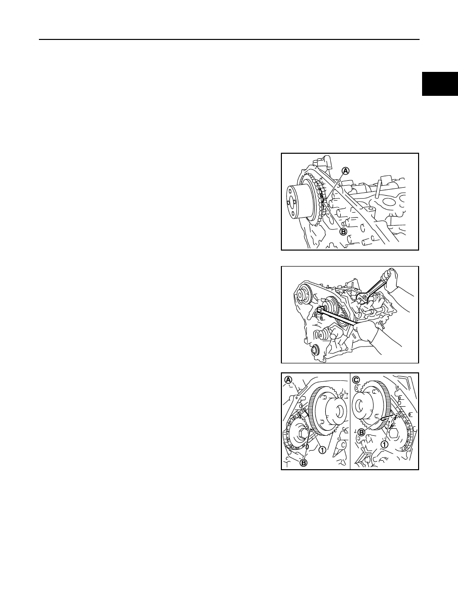
• It may be difficult to visually check the dislocation of mating

marks during and after installation. To make the matching eas-
ier, make a mating mark (A) on the top of sprocket teeth and
its extended line in advance with paint.

c.

After confirming the mating marks are aligned, tighten camshaft sprocket mounting bolts.
• Secure camshaft using wrench at the hexagonal portion to

tighten mounting bolts.

d.

Pull stopper pins (B) out from timing chain tensioners (second-
ary) (1).

9.

Install tension guide.

10. Install timing chain (primary) as follows:

Bank 1

: Use circle type.

Bank 2

: Use oval type.

B

: Mating mark (orange link)

JPBIA2260ZZ

KBIA1698J

A

:  Bank  1

C

:  Bank  2

JPBIA1727ZZ

EM-78

< UNIT DISASSEMBLY AND ASSEMBLY >

[VQ35DE]

TIMING CHAIN

a.

Install crankshaft sprocket (1).

• Check the mating marks on crankshaft sprocket face the front

of the engine.

b.

Install timing chain (primary).
• Install timing chain (primary) so the mating mark (punched) (B)

on camshaft sprocket (INT) (1) is aligned with the pink link (A)
on timing chain, while the mating mark (notched) (C) on crank-
shaft sprocket (2) is aligned with the orange link (D) on timing
chain, as shown in the figure.

• When it is difficult to align mating marks of timing chain (pri-

mary) with each sprocket, gradually turn camshaft using
wrench on the hexagonal portion to align it with the mating
marks.

• During alignment, be careful to prevent dislocation of mating

mark alignments of timing chains (secondary).

11. Install internal chain guide (1) and slack guide (2).

A

: Crankshaft side

B

: Engine front

C

: Mating mark (front side)

JPBIA0273ZZ

3

:  Water  pump

JPBIA1601ZZ

3

: Tension guide

JPBIA1104ZZ

TIMING CHAIN

EM-79

< UNIT DISASSEMBLY AND ASSEMBLY >

[VQ35DE]

C

D

E

F

G

H

I

J

K

L

M

A

EM

N

P

O

CAUTION:

Never over tighten slack guide mounting bolt (2). It is nor-
mal for a gap (A) to exist under the bolt seat when mounting
bolt is tightened to specification.

12. Install the timing chain tensioner (primary) with the following procedure:

a.

Pull plunger stopper tab (A) up (or turn lever downward) so as to
remove plunger stopper tab from the ratchet of plunger (D).
NOTE:
Plunger stopper tab and lever (C) are synchronized.

b.

Push plunger into the inside of tensioner body.

c.

Hold plunger in the fully compressed position by engaging
plunger stopper tab with the tip of ratchet.

d.

To secure lever, insert stopper pin (E) through hole of lever into
tensioner body hole (B).
• The lever parts and the tab are synchronized. Therefore, the

plunger will be secured under this condition.

NOTE:
Figure shows the example of 1.2 mm (0.047 in) diameter thin screwdriver being used as the stopper pin.

e.

Install timing chain tensioner (primary) (1).
• Remove any dirt and foreign materials completely from the

back and the mounting surfaces of timing chain tensioner (pri-
mary).

f.

Pull out stopper pin (A) after installing, and then release plunger.

13. Check again that the mating marks on each sprocket and each timing chain have not slipped out of align-

ment.

14. Install new O-rings (1) on rear timing chain case.

CAUTION:

Do not reuse O-rings.

15. Install new front oil seal on front timing chain case.

• Apply new engine oil to both oil seal lip and dust seal lip.

1

:  Slack  guide

3

: Cylinder block

JPBIA0117ZZ

JPBIA0118ZZ

JPBIA0119ZZ

A

:  Bank  1

B

:  Bank  2

JPBIA1111ZZ

EM-80

< UNIT DISASSEMBLY AND ASSEMBLY >

[VQ35DE]

TIMING CHAIN

• Install it so that each seal lip is oriented as shown in the figure. 

• Using a suitable drift [outer diameter: 60 mm (2.36 in)], press-

fit oil seal until it becomes flush with front timing chain case
end face.

• Check the garter spring is in position and seal lip is not

inverted.

16. Install front timing chain case as follows:

a.

Apply a continuous bead of liquid gasket with the tube presser
(commercial service tool) to front timing chain case back side as
shown in the figure.

Use Genuine RTV Silicone Sealant or equivalent. Refer to

GI-22, "Recommended Chemical Products and Sealants"

.

b.

Install front timing chain case as to fit its dowel pin hole together dowel pin on rear timing chain case.

A

: Oil seal lip

B

: Dust seal lip

: Engine inside

: Engine outside

JPBIA0054ZZ

PBIC0790E

D

:  Bolt  hole

E

: Protrusion

f

φ

2.6 - 3.6 mm (0.102 - 0.142 in)

JPBIA2472ZZ


Content   ..  580  581  582  583   ..