Nissan Quest E52. Manual - part 286


  Index      Nissan     Nissan Quest E52 (2011-2014 year) - Service and Repair Manual


Search            


Content   ..  284  285  286  287   ..


Nissan Quest E52. Manual - part 286


CO-14

< REMOVAL AND INSTALLATION >

RADIATOR

When removing components such as hoses, tubes/lines, etc., cap or plug openings to prevent fluid from spill-
ing.
1.

Drain engine coolant from radiator. Refer to 

CO-8, "Draining"

.

CAUTION:

• Perform this step when the engine is cold.
• Never spill engine coolant on drive belt.

2.

Remove the following parts:
• Air duct (inlet): Refer to 

EM-26, "Exploded View"

.

• Front grille: Refer to 

EXT-18, "Exploded View"

.

• Hood lock: Refer to 

DLK-459, "HOOD LOCK : Removal and Installation"

.

3.

Disconnect reservoir tank hose from radiator pipe (upper).

4.

Disconnect CVT fluid cooler hoses from radiator.
• Install blind plug to avoid leakage of CVT fluid.

5.

Separate low pressure flexible hose from low pressure pipe and move the separated hose. Refer to 

HA-

36, "LOW-PRESSURE FLEXIBLE HOSE : Removal and Installation"

.

6.

Remove radiator cap adapter and each radiator hoses (upper and lower) and radiator pipe (upper)
assembly.

CAUTION:

Be careful not to allow engine coolant to contact drive belt.

7.

Remove condenser. Refer to 

HA-43, "Exploded View"

.

CAUTION:

Be careful not to damage condenser core.
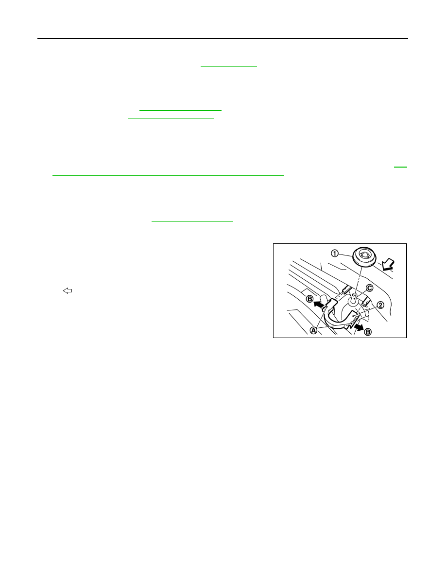
8.

Remove each radiator upper clips (2) by pulling the tabs (A) out-
side to release the lock (B) and then remove each mounting rub-
bers (upper) (1).

CAUTION:

Never pull the tabs outside excessively to prevent it from
damping.

9.

Lift up and remove radiator from front of radiator core support.

CAUTION:

Be careful not to damage or scratch on radiator core.

INSTALLATION

Note the following, and install in the reverse order of removal.

CAUTION:

Do not reuse O-ring.
NOTE:
When installing radiator core support (upper), check that the upper and lower mounts of radiator and air con-
denser are securely inserted in each mounting hole of radiator core support (upper and lower).

CAUTION:

Always use genuine bolts for cooling fan assembly mounting bolts and observe the tightening torque.
(To prevent damage to radiator)

Radiator Upper Clip

Install each radiator upper clips on radiator core connection as follows:

C

: Mounting pin

: Vehicle front

JPBIA1689ZZ

RADIATOR

CO-15

< REMOVAL AND INSTALLATION >

C

D

E

F

G

H

I

J

K

L

M

A

CO

N

P

O

1.

Install each mounting rubbers (upper) (1) on mounting pins (A)
of radiator.

2.

Align each radiator upper clips (2) with radiator core connection
(B), then insert each radiator upper clips straight into radiator
core connections until a click is heard.

3.

After connecting each radiator upper clips, use the following
method to check it is fully connected.
• Visually confirm that each radiator upper clips are connected

to radiator core connections.

• Move each radiator upper clips and the radiator forward and backward to check they are securely con-

nected.

Reservoir tank

NOTE:
Insert reservoir tank straight to the mounting position.

Radiator hose

NOTE:
Insert the radiator hose (1) all the way to the stopper (2) or by 33 mm (1.30 in) (hose without a stopper).

• For the orientation of the hose clamp pawl, refer to the figure.

*:Refer to the illustrations for the specific position each hose clamp tab.

: Vehicle front

JPBIA1690ZZ

unit: mm(in)

A.

Radiator side

B.

Engine side

Radiator hose

Hose end

Paint mark

Position of hose 

clamp*

Radiator hose (upper)

Radiator side

Right side

C

Radiator side (radiator pipe)

B

Engine side (radiator pipe)

C

Engine side

Upper

D

Radiator hose (lower)

Radiator side

Upper

A

Radiator side (radiator pipe)

A

Engine side (radiator pipe)

A

Engine side

Upper

E

JPBIA4294GB

CO-16

< REMOVAL AND INSTALLATION >

RADIATOR

• The angle (b) created by the hose clamp pawl and the specifiedline

(A) must be within 

±

30

°

as shown in the figure.

• To install hose clamps (1), check that the dimension (A) from the

end of the paint mark (2) on the radiator hose to the hose clamp is
within the reference value.

Inspection

INFOID:0000000009650546

INSPECTION AFTER INSTALLATION

• Check for leakage of engine coolant using the radiator cap tester adapter (commercial service tool) and the

radiator cap tester (commercial service tool). Refer to 

CO-8, "Inspection"

.

• Start and warm up the engine. Visually check that there is no leakage of engine coolant and CVT fluid.

F.

View F

g.

:45

°

:Vehicle upper

:Vehicle back side

JPBIA4777ZZ

JPBIA4295ZZ

Dimension "A"

(-1) - (+1) mm

(-0.04) - (+0.04) in

JSBIA0241ZZ

COOLING FAN

CO-17

< REMOVAL AND INSTALLATION >

C

D

E

F

G

H

I

J

K

L

M

A

CO

N

P

O

COOLING FAN

Exploded View

INFOID:0000000009650547

Removal and Installation

INFOID:0000000009650548

REMOVAL

1.

Remove the following parts.
• Engine under cover
• Air duct (inlet): Refer to 

EM-26, "Exploded View"

.

• Oil level gauge: Refer to 

EM-93, "Exploded View"

.

• Battery and battery tray: Refer to 

PG-105, "Removal and Installation"

.

2.

Drain engine coolant from radiator. Refer to 

CO-8, "Draining"

.

CAUTION:

• Perform this step engine is cold.
• Never spill engine coolant on drive belt.

3.

Remove radiator cap adapter and each radiator hoses (upper) and radiator pipe (upper) assembly. Refer
to 

CO-13, "Exploded View"

.

4.

Disconnect harness connector from crash zone sensor, and move harness to aside. Refer to 

SR-23,

"Exploded View"

.

5.

Disconnect harness connector from fan motors (RH and LH), and move harness to aside.

6.

Remove cooling fan assembly.

1.

Fan motor (LH)

2.

Fan motor (RH)

3.

Fan shroud

4.

Mounting rubber

5.

Cooling fan (RH)

6.

Cooling fan (LH)

A.

Apply on fan motor shaft

: Vehicle front


: Apply genuine high strength thread locking sealant or equivalent.

 : N·m (kg-m, in-lb)

JPBIA1687GB


Content   ..  284  285  286  287   ..