Content .. 1017 1018 1019 1020 ..
Nissan Quest E52. Manual - part 1019
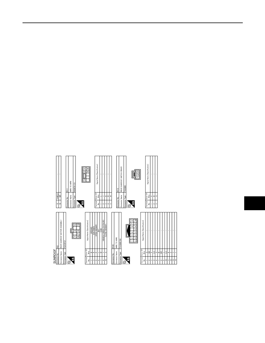
SUNROOF MOTOR ASSEMBLY
RF-19
< WIRING DIAGRAM >
C
D
E
F
G
H
I
J
L
M
A
B
RF
N
O
P
JRKWC6565GB
|
|
|
Content .. 1017 1018 1019 1020 ..
SUNROOF MOTOR ASSEMBLY RF-19 < WIRING DIAGRAM > C D E F G H I J L M A B RF N O P JRKWC6565GB |