Content .. 1001 1002 1003 1004 ..
Nissan Quest E52. Manual - part 1003
PWC-124
< REMOVAL AND INSTALLATION >
[DRIVER SIDE WINDOW ANTI-PINCH]
SLIDING DOOR POWER WINDOW SWITCH
SLIDING DOOR POWER WINDOW SWITCH
Removal and Installation
INFOID:0000000009653408
REMOVAL
1.
Remove sliding door finisher. Refer to
.
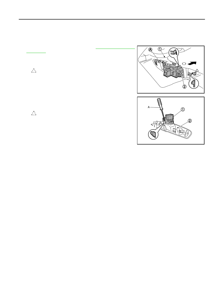
2.
Remove screw (A), disconnect pawls from sliding door finisher
(1), and then remove power window switch finisher (2).
3.
Remove power window switch (1) from power window switch fin-
isher (2) using a remover tool (A).
INSTALLATION
Install in the reverse order of removal.
: Pawl
JMKIA8165ZZ
: Pawl
JMKIA8166ZZ