Nissan Cube. Manual - part 404
EM-20
< PERIODIC MAINTENANCE >
CAMSHAFT VALVE CLEARANCE
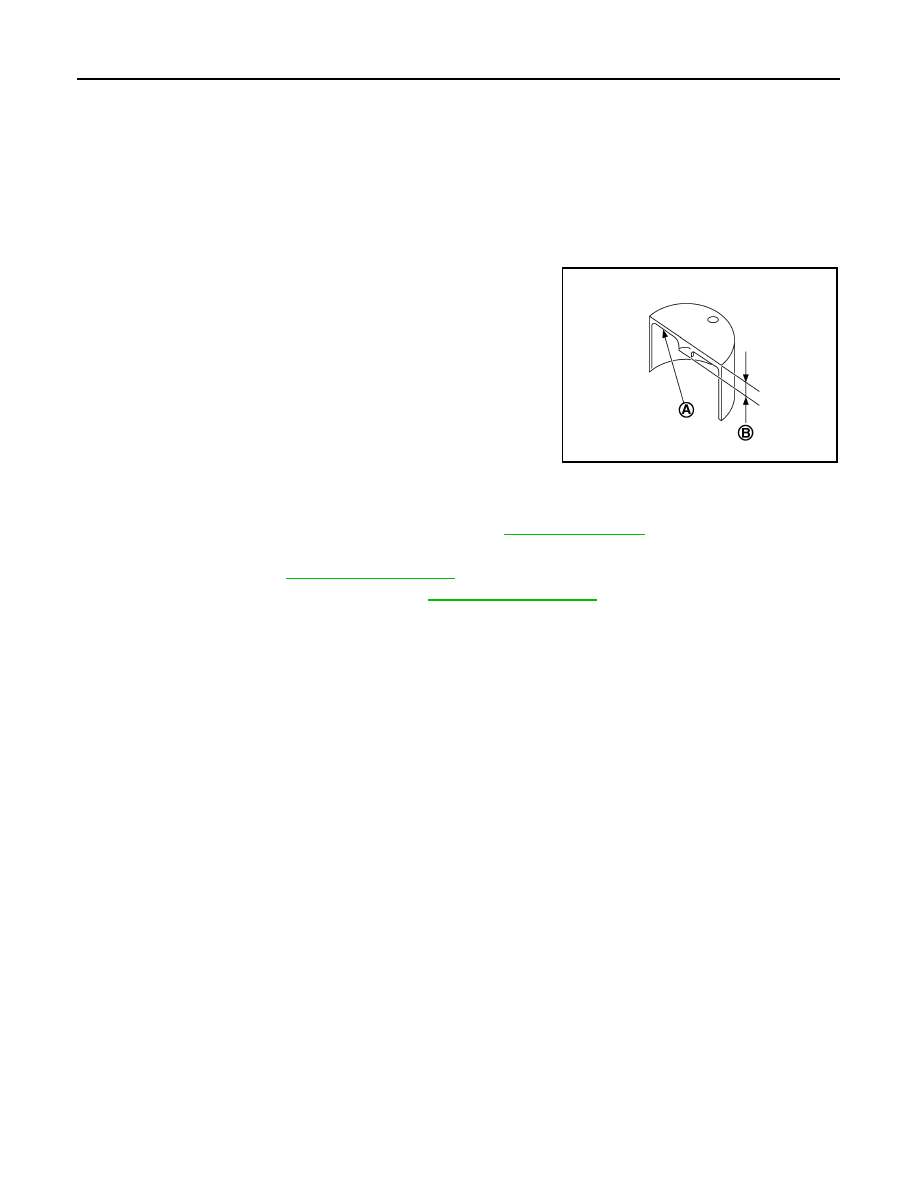
• Thickness of new valve lifter (B) can be identified by stamp
mark (A) on the reverse side (inside the cylinder).
• Stamp mark “302” indicates 3.02 mm (0.1189 in) in thickness.
NOTE:
Available thickness of valve lifter: 26 sizes range 3.00 to 3.50 mm (0.1181 to 0.1378 in) in steps of 0.02
mm (0.0008 in) (when manufactured at factory). Refer to
5.
Install the selected valve lifter.
6.
Install camshaft. Refer to
.
7.
Install timing chain and related parts. Refer to
.
8.
Manually rotate crankshaft pulley a few rotations.
9.
Check that the valve clearances is within the standard. Refer to “INSPECTION”.
10. Install remaining parts in the reverse order of removal.
11. Warm up the engine, and check for unusual noise and vibration.
Valve lifter thickness calculation:
t = t
1
+ (C
1
– C
2
)
t
= Valve lifter thickness to be replaced
t
1
= Removed valve lifter thickness
C
1
= Measured valve clearance
C
2
= Standard valve clearance:
Intake
: 0.30 mm (0.012 in)
Exhaust
: 0.33 mm (0.013 in)
PBIC3196J