Nissan Versa Sedan. Manual - part 836
 

  Index      Nissan     Nissan Versa Sedan (2014 year) - Service and Repair Manual


Search            


Content   ..  834  835  836  837   ..


Nissan Versa Sedan. Manual - part 836


TM-250

< UNIT REMOVAL AND INSTALLATION >

[4AT: RE4F03C]

TRANSMISSION ASSEMBLY

UNIT REMOVAL AND INSTALLATION

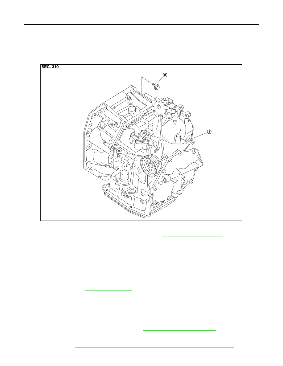
TRANSMISSION ASSEMBLY

Exploded View

INFOID:0000000009268040

Removal and Installation

INFOID:0000000009268041

WARNING:

• Do not open the radiator cap or drain plug when the engine is hot. Hot liquid may spray out, causing

serious injury.

• Perform these steps after the coolant temperature has cooled sufficiently.

NOTE:

• When replacing the TCM and transaxle assembly as a set, replace the transaxle assembly first and then

replace the TCM. Refer to 

TM-124, "Description"

.

• When replacing components such as hoses, tubes/lines, etc., cap or plug openings to prevent fluid from

spilling.

REMOVAL

1. Remove the TCM. Refer to 

TM-241, "Removal and Installation"

.

2. Remove the battery plate.
3. Remove the air duct and air cleaner case. Refer to 

EM-25, "Removal and Installation"

.

4. Disconnect the harness connectors from the following components and remove the harness from the tran-

saxle.

• A/T unit. Refer to 

TM-61, "Removal and Installation Procedure for A/T Assembly Connector"

.

1.

Transaxle assembly

A. : Tightening must be done following the installation procedure. Refer to 

TM-250, "Removal and Installation"

.

JSDIA1938ZZ

TRANSMISSION ASSEMBLY

TM-251

< UNIT REMOVAL AND INSTALLATION >

[4AT: RE4F03C]

C

E

F

G

H

I

J

K

L

M

A

B

TM

N

O

P

• Transmission range switch

• Input speed sensor

• Output speed sensor

• Crankshaft position sensor. Refer to 

EM-56, "Exploded View"

.

• Ground

5. Remove the control cable from the transaxle assembly. Refer to 

TM-236, "Removal and Installation"

.

6. Disconnect the fluid cooler hose from the fluid cooler tube. Refer to 

TM-247, "Removal and Installation"

.

7. Remove the left and right drive shafts. Refer to 

FAX-15, "Removal and Installation"

.

8. Remove the drive shaft heat insulator.
9. Remove starter motor. Refer to 

STR-31, "Removal and Installation"

.

10. Reposition the fender protectors out of the way. Refer to 

EXT-26, "Removal and Installation"

.

11. Rotate the crankshaft and remove the nuts that secure the drive plate to the torque converter.

CAUTION:

Rotate crankshaft clockwise (as viewed from the front of the engine).

12. Remove the rear torque rod. Refer to 

EM-82, "Exploded View"

.

13. Set a transmission jack under the transaxle assembly.

CAUTION:

Be careful not to contact the drain plug when setting the transmission jack.

14. Set a transmission jack under the engine assembly.

CAUTION:

Be careful not to contact the drain plug when setting the transmission jack.

15. Remove the left engine mounting insulator. Refer to 

EM-82, "Exploded View"

.

16. Remove the left engine mounting bracket (LH). Refer to 

EM-82, "Exploded View"

.

17. Remove the bolts that fasten the transaxle assembly and engine assembly.
18. Remove the transaxle assembly from the vehicle.

CAUTION:

Do not drop the torque converter.

INSTALLATION

Installation is in the reverse order of removal.

CAUTION:

• Do not reuse O-ring or copper sealing washers. 

• Apply ATF to the O-ring.

• When installing the transaxle assembly onto the engine assembly,

check the engagement of the dowel pins (

).

• When using suitable tool (A) for alignment, install it to the align-

ment stud bolt used to align the torque converter to the drive plate.

JSDIA1184ZZ

JPDIA0683ZZ

TM-252

< UNIT REMOVAL AND INSTALLATION >

[4AT: RE4F03C]

TRANSMISSION ASSEMBLY

• Rotate the crankshaft so that the alignment hole (A) of drive plate

aligns with the position of the torque converter alignment stud bolt.

CAUTION:

• Rotate the crankshaft clockwise (as viewed from the front of

the engine).

• Be careful that torque converter stud bolts are aligned to the

drive plate holes. Otherwise the stud bolts contact the drive

plate.

• Insert the alignment stud bolt of torque converter into the align-

ment hole of the drive plate, aligning the drive plate holes with the

torque converter stud bolts.

CAUTION:

Be careful not to strike the drive plate with the torque converter stud bolts.

• When installing the torque converter nuts, temporarily tighten the nuts. Then, after installing the engine and

transaxle assembly bolts tighten the nuts to the specified torque.

CAUTION:

• Rotate the crankshaft clockwise (as viewed from the front of the engine).

• Check the tightening torque for the crankshaft pulley bolts after the bolts fastening the drive plate

and torque converter have been tightened and the crankshaft pulley bolts have been secured.

Refer to 

EM-82, "Exploded View"

.

• Install the transaxle assembly and engine assembly bolts accord-

ing to the following standards.

Inspection and Adjustment

INFOID:0000000009268042

INSPECTION BEFORE INSTALLATION

Check the distance (A) between the converter housing and torque

converter.

Tightening torque

: 51 N·m (5.2 kg-m, 38 ft-lb)

JPDIA0684ZZ

JSDIA1839ZZ

Bolt No.

A

B

C

D

Direction of insertion

Transaxle assembly 

→ 

Engine assembly

Engine assembly 

→ Transaxle assembly

Number  of  bolts

2

2

1

3

Bolt length mm (in)

40 (1.57)

44 (1.73)

69 (2.72)

49 (1.93)

Tightening torque
N·m (kg-m, ft-lb)

48.0 (4.9, 35)

(B)

: Scale

(C)

: Straightedge

Dimension (A)

TM-255, "Torque Converter"

JSDIA1840ZZ

TRANSMISSION ASSEMBLY

TM-253

< UNIT REMOVAL AND INSTALLATION >

[4AT: RE4F03C]

C

E

F

G

H

I

J

K

L

M

A

B

TM

N

O

P

INSPECTION AFTER INSTALLATION

Check the following items:

• A/T fluid leakage, refer to 

TM-230, "Inspection"

.

• For the A/T positions, refer to 

TM-235, "Inspection and Adjustment"

• Start the engine and check for coolant leakage from the parts which are removed and reinstalled.

ADJUSTMENT AFTER INSTALLATION

• Check the A/T fluid level. Refer to 

TM-231, "Adjustment"

.

• Perform “TRANSAXLE ASSEMBLY REPLACEMENT”. Refer to 

TM-124, "Description"

.


Content   ..  834  835  836  837   ..