Nissan Versa Sedan. Manual - part 751
 

  Index      Nissan     Nissan Versa Sedan (2014 year) - Service and Repair Manual


Search            


Content   ..  749  750  751  752   ..


Nissan Versa Sedan. Manual - part 751


ST-6

< BASIC INSPECTION >

STEERING WHEEL

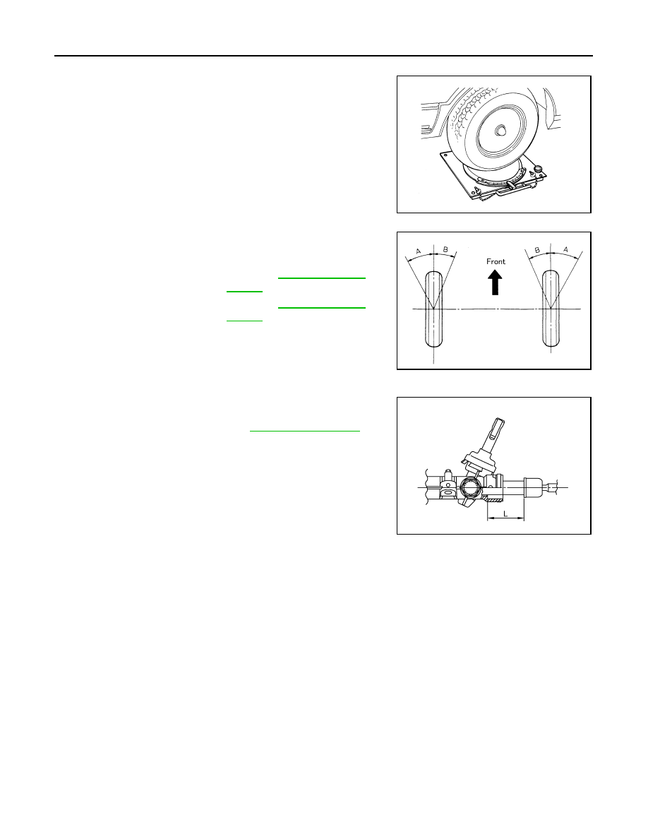
Perform front wheel turning angle inspection, after toe-in inspection.

2. Place front wheels on turning radius gauges and rear wheels on

stands, so that vehicle can be level.

3. Check the maximum inner and outer wheel turning angles for LH

and RH road wheels.

• With the engine at idle, turn steering wheel from full left stop to

full right stop and measure the turning angles.

• Check the following items when turning angle is out of the standard.

- Check rack stroke (L).

- Disassemble steering gear assembly to check the cause that

rack stroke is outside of the standard.

• Steering angles are not adjustable. Check steering gear

assembly, steering column assembly and front suspension

components for wear or damage if any of the turning angles

are different from the specified value. Replace any of them, if

any non-standard condition exists.

FAA0016D

Inner wheel (Angle: A)

: Refer to 

ST-19, "Steering 

Angle"

.

Outer wheel (Angle: B)

: Refer to 

ST-19, "Steering 

Angle"

.

SGIA0055E

Rack stroke (L)

: Refer to 

ST-20, "Rack Stroke"

.

JSGIA0272ZZ

NOISE, VIBRATION AND HARSHNESS (NVH) TROUBLESHOOTING

ST-7

< SYMPTOM DIAGNOSIS >

C

D

E

F

H

I

J

K

L

M

A

B

ST

N

O

P

SYMPTOM DIAGNOSIS

NOISE, VIBRATION AND HARSHNESS (NVH) TROUBLESHOOTING

NVH Troubleshooting Chart

INFOID:0000000009266809

Use the chart below to find the cause of the symptom. If necessary, repair or replace these parts.

×: Applicable

Reference page

ST

-1

5, "Ins

pe

ct

io

n"

ST

-1

5, "Ins

pe

ct

io

n"

ST

-1

5, "Ins

pe

ct

io

n"

ST

-5

, "In

spec

tion

"

ST

-5

, "In

spec

tion

"

ST

-9,

 "Rem

ov

al

 an

Ins

ta

lla

tio

n"

ST

-1

4, "Exp

lo

de

V

ie

w

"

ST

-1

0, "Ins

pe

ct

io

n"

ST

-9,

 "Exp

lo

de

d V

ie

w

"

ST

-1

4, "Exp

lo

de

V

ie

w

"

FAX-6

, "NVH T

rou

ble

sh

oo

tin

g Chart

"

RA

X-4, 

"NVH T

ro

ubl

es

ho

ot

ing

 Cha

rt"

FSU-5,

 "NVH T

ro

ub

les

ho

ot

ing

 Ch

art"

RS

U-4

, "

N

V

H

 T

rou

bl

es

ho

oti

ng

 Cha

rt"

WT

-3

7, 

"NVH T

ro

ubl

es

ho

ot

ing

 Cha

rt"

WT

-3

7, 

"NVH T

ro

ubl

es

ho

ot

ing

 Cha

rt"

FAX-6

, "NVH T

rou

ble

sh

oo

tin

g Chart

"

BR-7, 

"NVH T

rou

bl

es

ho

oti

ng

 Cha

rt"

Possible cause and SUSPECTED PARTS

Ou

ter/

inn

er 

so

ck

et

 ba

ll 

joi

nt

 swi

ng

ing

 to

rqu

e

O

u

ter/

inn

er 

so

ck

et

 ba

ll 

joi

nt

 rot

ati

ng

 to

rque

O

u

ter/

inn

er 

so

ck

et

 ba

ll 

joi

nt

 en

d p

la

y

S

te

e

ring

 whe

e

l pl

ay

Im

pro

p

er

 st

ee

ring

 wh

ee

l

Im

p

rop

er i

ns

tal

la

tio

n o

r lo

os

en

es

s of

 til

t l

oc

k l

ev

er

M

ou

nt

ing

 loos

e

nes

s

S

tee

rin

g c

o

lum

de

form

at

ion

 o

r da

ma

ge

Im

p

rop

er i

ns

tal

la

tio

n o

r lo

os

en

es

s of

 st

ee

ring

 c

olu

m

n

S

te

eri

ng

 li

nk

ag

e l

oo

se

ne

ss

A

XLE and 

SUSP

ENSION

TI

RE

ROAD W

H

EEL

DRIV

E SHAFT

BR

AK

E

Symptom

Noise

×

×

×

×

×

×

×

×

×

×

×

Shake

×

×

×

×

×

×

×

×

Vibration

×

×

×

×

×

×

×

×

Shimmy

×

×

×

×

×

×

×

Shudder

×

×

×

×

×

×

×

ST-8

< REMOVAL AND INSTALLATION >

STEERING WHEEL

REMOVAL AND INSTALLATION

STEERING WHEEL

Exploded View

INFOID:0000000009266810

Removal and Installation

INFOID:0000000009266811

REMOVAL

NOTE:

When reconnecting spiral cable, secure cable with a tape so that case and rotating part stay aligned. This will

omit neutral position alignment procedure during spiral cable installation.
1. Set vehicle to the straight-ahead position.
2. Remove driver air bag module. Refer to 

SR-11, "Removal and Installation"

.

3. Remove steering wheel lock nut after steering is locked.
4. Remove steering wheel using a suitable tool (A).

INSTALLATION

Installation is in the reverse order of removal.

• Check the spiral cable neutral position after replacing or rotating spiral cable. Refer to 

SR-14, "Removal and

Installation"

.

CAUTION:

• Do not twist spiral cable excessively after it becomes tight. (Twisting may cause the cable to be

torn off.)

• Do not reuse steering wheel lock nut.

1.

Steering wheel

JSGIA0704GB

JSGIA0654ZZ

STEERING COLUMN

ST-9

< REMOVAL AND INSTALLATION >

C

D

E

F

H

I

J

K

L

M

A

B

ST

N

O

P

STEERING COLUMN

Exploded View

INFOID:0000000009266812

Removal and Installation

INFOID:0000000009266813

REMOVAL

CAUTION:

• Keep steering column assembly away from magnetic sources.

• Do not disassemble steering column assembly.

• While removing the steering column assembly, do not move the steering gear.

• When removing the steering column assembly, be careful not to allow the intermediate shaft to turn.
1. Set vehicle to the straight-ahead position.
2. Place the steering column tilt to the lowest selection.
3. Remove instrument lower panel LH. Refer to 

IP-20, "Removal and Installation"

.

4. Remove driver air bag module. Refer to 

SR-11, "Removal and Installation"

.

5. Remove steering wheel. Refer to 

ST-8, "Exploded View"

.

6. Remove steering column covers. Refer to 

IP-15, "Removal and Installation"

.

7. Remove spiral cable. Refer to 

SR-14, "Removal and Installation"

.

8. Remove combination switch. Refer to 

EXL-107, "Exploded View"

9. Remove the cluster lid A. Refer to 

IP-19, "Removal and Installation"

10. Disconnect the harness connectors from the steering switch.
11. Remove the key cylinder only if the steering column is being replaced. Refer to 

TM-435, "Removal and

Installation"

.  

12. Place the steering column tilt to the middle selection.

CAUTION:

Do not change the position of the tilt mechanism until the steerign column is reinstalled.

13. Loosen the steering shaft lower joint bolt.
14. Remove the intermediate shaft upper bolt and separate intermediate shaft from steering column assem-

bly. Refer to 

ST-12, "Removal and Installation"

.

CAUTION:

• Place a matching mark on both intermediate shaft and steering column assembly before remov-

ing intermediate shaft.

1.

Steering column assembly

2.

Clamp

JPGIA0110GB


Content   ..  749  750  751  752   ..