Nissan Note E12. Manual - part 560


  Index      Nissan     Nissan Note E12 - Service and Repair Manual


Search            


Content   ..  558  559  560  561   ..


Nissan Note E12. Manual - part 560


SEC-92

< DTC/CIRCUIT DIAGNOSIS >

B2608 STARTER RELAY

3.

CHECK STARTER RELAY CIRCUIT

1. Turn ignition switch OFF.

2. Disconnect starter relay.

3. Disconnect BCM connector.

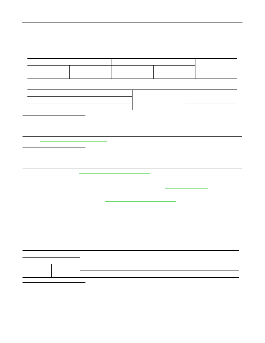
4. Check continuity between starter relay harness connector and BCM harness connector.

5. Check continuity between starter relay harness connector and ground.

Is the inspection result normal?

YES

>> GO TO 5.

NO

>> Repair or replace harness.

4.

CHECK STARTER RELAY

Refer to 

SEC-92, "Component Inspection"

.

Is the inspection result normal?

YES

>> GO TO 5.

NO

>> Replace starter relay.

5.

REPLACE BCM

1. Replace BCM. Refer to 

BCS-67, "Removal and Installation"

.

2. Perform initialization of BCM and registration of all Intelligent Keys using CONSULT. Refer to the CON-

SULT Immobilizer mode and follow the on-screen instructions.

3. Perform DTC CONFIRMATION PROCEDURE for B2605. Refer to 

SEC-89, "DTC Logic"

.

Is DTC B2605 detected again?

YES

>> Replace IPDM E/R. Refer to 

PCS-30, "Removal and Installation"

.

NO

>> Inspection End.

Component Inspection

INFOID:0000000009567450

1.

CHECK STARTER RELAY

1. Turn ignition switch OFF.

2. Disconnect starter relay.

3. Check continuity between starter relay terminals.

Is the inspection result normal?

YES

>> Inspection End.

NO

>> Replace starter relay.

Starter relay

BCM

Continuity

Connector

Terminal

Connector

Terminal

E41

1

M98

97

Yes

Starter relay

Ground

Continuity

Connector

Terminal

E41

1

No

Starter relay

Condition

Continuity

Terminal

3

5

12 V direct current supply between terminals 1 and 2

Yes

No current supply

No

B260F ENGINE STATUS

SEC-93

< DTC/CIRCUIT DIAGNOSIS >

C

D

E

F

G

H

I

J

L

M

A

B

SEC

N

O

P

B260F ENGINE STATUS

Description

INFOID:0000000009567451

BCM receives the engine status signal from ECM via CAN communication.

DTC Logic

INFOID:0000000009567452

DTC DETECTION LOGIC

NOTE:

• If DTC B260F is displayed with DTC U1000, first perform the trouble diagnosis for DTC U1000. Refer to

BCS-57, "DTC Logic"

.

• If DTC B260F is displayed with DTC U1010, first perform the trouble diagnosis for DTC U1010. Refer to

BCS-58, "DTC Logic"

.

DTC CONFIRMATION PROCEDURE

1.

PERFORM DTC CONFIRMATION PROCEDURE

1. Turn ignition switch ON and wait 2 seconds or more.

2. Check DTC in Self Diagnostic Result mode of BCM using CONSULT.
Is DTC detected?

YES

>> Go to 

SEC-93, "Diagnosis Procedure"

.

NO

>> Inspection End.

Diagnosis Procedure

INFOID:0000000009567453

1.

INSPECTION START

1. Turn ignition switch ON.

2. Select Self Diagnostic Result mode of BCM using CONSULT.

3. Touch ERASE.

4. Perform DTC CONFIRMATION PROCEDURE for DTC B260F. Refer to 

SEC-93, "DTC Logic"

.

Is DTC detected?

YES

>> GO TO 2.

NO

>> Inspection End.

2.

REPLACE ECM

1. Replace ECM.

Refer to 

EC-338, "Removal and Installation"

.

2. Perform “ADDITIONAL SERVICE WHEN REPLACING ECM”.

Refer to 

EC-111, "Work Procedure"

.

>> Inspection End.

DTC No.

Trouble diagnosis name

DTC detecting condition

Possible cause

B260F

ECM CAN COMM

BCM has not yet received the engine status 
signal from ECM when ignition switch is in 
the ON position.

• Harness or connectors

(The CAN communication line is open 
or shorted.)

• ECM

SEC-94

< DTC/CIRCUIT DIAGNOSIS >

B261F ASCD CLUTCH SWITCH

B261F ASCD CLUTCH SWITCH

DTC Logic

INFOID:0000000009606317

DTC DETECTION LOGIC

NOTE:

• If DTC B261F is displayed with DTC U1000, first perform the trouble diagnosis for DTC U1000. Refer to

BCS-57, "DTC Logic"

.

• If DTC B261F is displayed with DTC U1010, first perform the trouble diagnosis for DTC U1010. Refer to

BCS-58, "DTC Logic"

.

DTC CONFIRMATION PROCEDURE

1.

PERFORM DTC CONFIRMATION PROCEDURE

1. Start the engine.

2. Drive vehicle at a speed of 40 km/h (24.8 MPH) or more for 10 seconds.

3. Decrease the vehicle speed to below 40 km/h (24.8 MPH).

4. Repeat steps 2 and 3 twice (total of 3 times).

5. Check DTC in “Self Diagnostic Result” mode of “BCM” using CONSULT.
Is DTC detected?

YES >> Go 

to 

SEC-94, "Diagnosis Procedure"

.

NO

>> Inspection End

Diagnosis Procedure

INFOID:0000000009606318

Regarding Wiring Diagram information, refer to 

SEC-24, "Wiring Diagram"

.

1.

CHECK DTC OF COMBINATION METER

Check DTC in “Self Diagnostic Result” mode of “METER/M&A” using CONSULT.

Refer to 

MWI-20, "DTC Index"

.

Is the inspection result normal?

YES

>> GO TO 2.

NO

>> Repair or replace the malfunctioning parts.

2.

CHECK FUSE

1. Turn power switch OFF.

2. Check that the following fuse in the fuse block (J/B) is not blown.

Is the inspection result normal?

YES

>> GO TO 3.

NO

>> Replace the blown fuse after repairing the cause of blowing.

DTC No.

CONSULT screen items

(Trouble diagnosis content)

DTC detecting condition

Possible cause

B261F

ASCD CNCL/CLTCH SW
(ASCD clutch interlock 
switch)

BCM detects the following status for 10 seconds 
3 times
• Clutch interlock switch input: 0 V
• Vehicle speed: 40 km/h (24.8 MPH) or more

• Harness or connectors.

(CAN communication line is open 
or shorted.)

• Harness or connectors.

(Clutch interlock switch circuit is 
open or shorted)

• Clutch interlock switch
• Combination meter
• BCM 

Signal name

Fuse No.

Ignition power supply

10 (10 A)

B261F ASCD CLUTCH SWITCH

SEC-95

< DTC/CIRCUIT DIAGNOSIS >

C

D

E

F

G

H

I

J

L

M

A

B

SEC

N

O

P

3.

CHECK CLUTCH INTERLOCK SWITCH POWER SUPPLY

1. Disconnect clutch interlock switch connector.

2. Turn ignition switch ON.

3. Check voltage between clutch interlock switch harness connector and ground.

Is the inspection result normal?

YES

>> GO TO 4.

NO

>> Repair or replace harness.

4.

CHECK CLUTCH INTERLOCK SWITCH SIGNAL 

1. Connect clutch interlock switch connector.

2. Check voltage between BCM harness connector and ground.

Is the inspection result normal?

YES

>> GO TO 5.

NO

>> GO TO 6.

5.

REPLACE BCM

1. Replace BCM. Refer to 

BCS-67, "Removal and Installation"

.

2. Perform initialization of BCM and registration of all Intelligent Keys using CONSULT. Refer to the CON-

SULT Immobilizer mode and follow the on-screen instructions.

>> Inspection End

6.

CHECK CLUTCH INTERLOCK SWITCH CIRCUIT

1. Turn ignition switch OFF.

2. Disconnect BCM connector.

3. Check continuity between clutch interlock switch harness connector and BCM harness connector.

Is the inspection result normal?

YES

>> GO TO 7.

NO

>> Repair or replace harness.

7.

CHECK CLUTCH INTERLOCK SWITCH

Refer to 

SEC-96, "Component Inspection"

.

Is the inspection result normal?

YES

>> GO TO 8.

NO

>> Replace clutch interlock switch. Refer to 

CL-10, "Exploded View"

.

8.

CHECK INTERMITTENT INCIDENT

Refer to 

GI-41, "Intermittent Incident"

.

(+)

(–)

Voltage (V)

(Approx.)

Clutch interlock switch

Connector

Terminal

E34

1

Ground

Battery voltage

(+)

(–)

Condition

Voltage

BCM

Connector

Terminal

M98

101

Ground

Clutch pedal

Released

6 – 16 V

Depressed

0 – 1.5 V

Clutch interlock switch

BCM

Continuity

Connector

Terminal

Connector

Terminal

E34

2

M98

101

Yes


Content   ..  558  559  560  561   ..