Nissan Note E12. Manual - part 453


  Index      Nissan     Nissan Note E12 - Service and Repair Manual


Search            


Content   ..  451  452  453  454   ..


Nissan Note E12. Manual - part 453


MIR-16

< REMOVAL AND INSTALLATION >

DOOR MIRROR

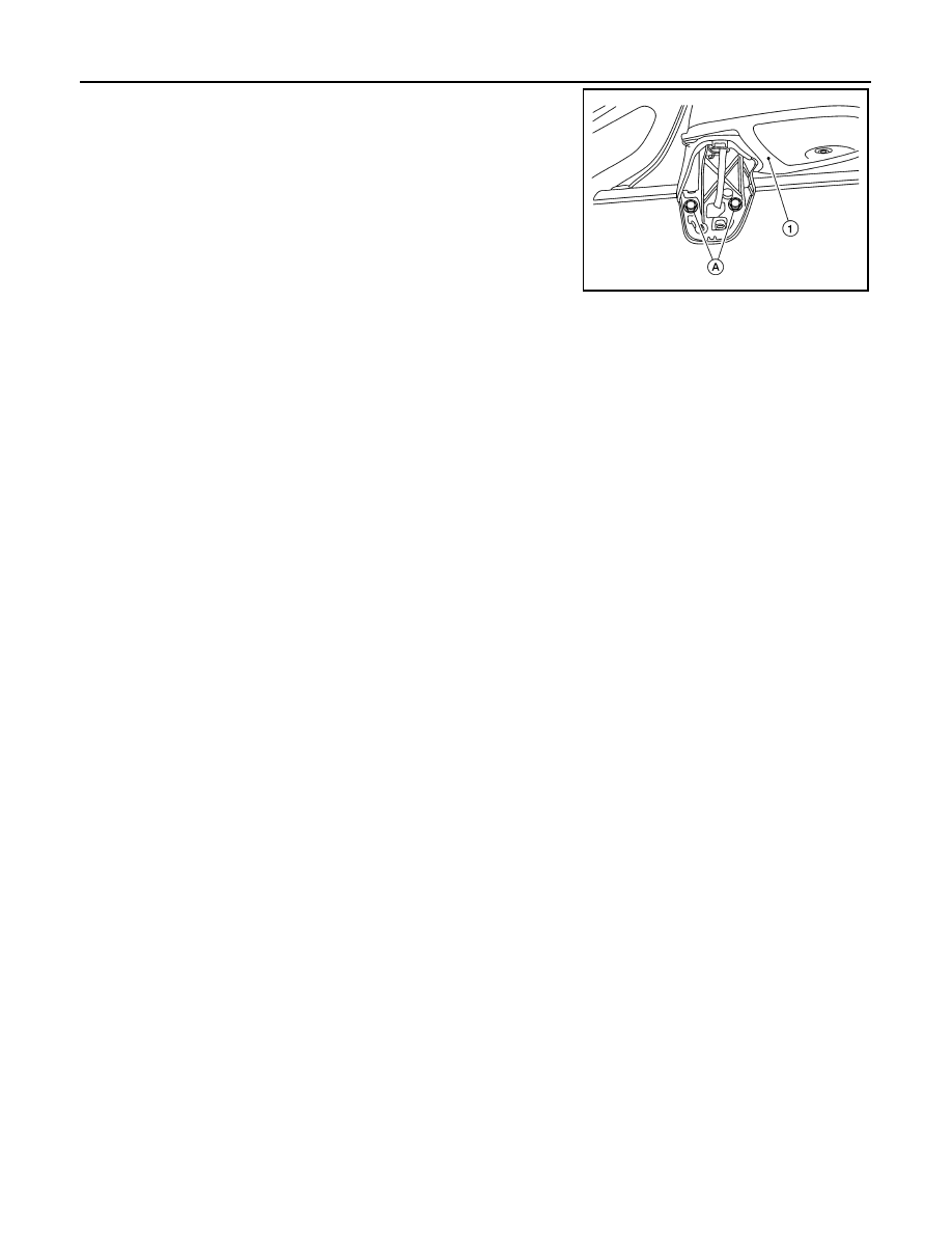
7. Remove the door mirror outer bolts (A) and the door mirror (1).

INSTALLATION

Installation is in the reverse order or removal.

CAUTION:

Visually check door mirror base cover pawls for deformation and damage during installation. 

AWLIA2181ZZ

DOOR MIRROR REAR FINISHER

MIR-17

< REMOVAL AND INSTALLATION >

C

D

E

F

G

H

I

J

K

M

A

B

MIR

N

O

P

DOOR MIRROR REAR FINISHER

Removal and Installation

INFOID:0000000009671236

REMOVAL

1. Remove door mirror glass.
a. Tilt the door mirror glass upward.
b. Remove door mirror glass by placing a suitable tool in the recesses between door mirror glass and actua-

tor and rotating (twisting) to releasing the pawls. 

2. Disconnect the harness connector (if equipped) from the door mirror glass.
3. Remove actuator screws (A) using a suitable tool (B) and

remove actuator.

NOTE:

Actuator is removed only to access door mirror rear finisher

pawls. It is not a serviceable component. 

4. Release pawls using a suitable tool (C) and remove door mirror

rear finisher (1) from the door mirror (2).

: Pawl

INSTALLATION

Installation is in the reverse order of removal.

CAUTION:

Visually check door mirror rear finisher pawls for deformation and damage during installation. 

AWLIA2179ZZ

MIR-18

< REMOVAL AND INSTALLATION >

DOOR MIRROR REMOTE CONTROL SWITCH

DOOR MIRROR REMOTE CONTROL SWITCH

Removal and Installation

INFOID:0000000009014900

REMOVAL

1. Remove the instrument lower panel LH. Refer to 

IP-24, "Removal and Installation"

.

2. Remove door mirror remote control switch (1) from the instru-

ment lower panel LH using a suitable tool.

: Pawl

INSTALLATION

Installation is in the reverse order of removal.

AWLIA2157ZZ

MWI

MWI-1

DRIVER INFORMATION & MULTIMEDIA

C

D

E

F

G

H

I

J

K

L

M

B

SECTION 

MWI

A

O

P

CONTENTS

METER, WARNING LAMP & INDICATOR

PRECAUTION ...............................................

3

PRECAUTIONS ...................................................

3

Precaution for Supplemental Restraint System 
(SRS) "AIR BAG" and "SEAT BELT PRE-TEN-
SIONER" .................................................................
..

3

PREPARATION ............................................

4

PREPARATION ...................................................

4

Commercial Service Tools  ........................................

4

SYSTEM DESCRIPTION  ..............................

5

COMPONENT PARTS  ........................................

5

METER SYSTEM .........................................................

5

METER SYSTEM : Component Parts Location  ........

5

METER SYSTEM : Combination Meter  ....................

6

SYSTEM ..............................................................

7

METER SYSTEM .........................................................

7

METER SYSTEM : System Description ....................

7

METER SYSTEM : Fail-safe .....................................

8

SPEEDOMETER ..........................................................

9

SPEEDOMETER : System Description .....................

9

TACHOMETER ............................................................

9

TACHOMETER : System Description .......................

9

SHIFT POSITION INDICATOR ....................................

9

SHIFT POSITION INDICATOR : System Descrip-
tion ..........................................................................

10

OIL PRESSURE WARNING LAMP ...........................

10

OIL PRESSURE WARNING LAMP : System De-
scription ...................................................................

10

METER ILLUMINATION CONTROL  .........................

10

METER ILLUMINATION CONTROL : System De-
scription ...................................................................

10

INFORMATION DISPLAY ..........................................

11

INFORMATION DISPLAY : System Description  .....

11

OPERATION .....................................................

13

Switch Name and Function ......................................

13

DIAGNOSIS SYSTEM (COMBINATION 
METER) .............................................................

14

On Board Diagnosis Function ..................................

14

CONSULT Function .................................................

15

ECU DIAGNOSIS INFORMATION ..............

17

COMBINATION METER  ...................................

17

Reference Value ......................................................

17

Fail-safe ...................................................................

19

DTC Index  ...............................................................

20

BCM (BODY CONTROL MODULE)  .................

21

List of ECU Reference .............................................

21

WIRING DIAGRAM ......................................

22

METER SYSTEM  ..............................................

22

Wiring Diagram ........................................................

22

BASIC INSPECTION  ...................................

33

DIAGNOSIS AND REPAIR WORK FLOW  .......

33

Work Flow ................................................................

33

DTC/CIRCUIT DIAGNOSIS  .........................

34

U1000 CAN COMM CIRCUIT  ...........................

34

DTC Logic ................................................................

34

Diagnosis Procedure ..............................................

34

U1010 CONTROL UNIT (CAN) .........................

35

Description ...............................................................

35

DTC Logic ................................................................

35

Diagnosis Procedure  ...............................................

35

B2205 VEHICLE SPEED ..................................

36


Content   ..  451  452  453  454   ..