Nissan Note E12. Manual - part 302
EXL-76
< DTC/CIRCUIT DIAGNOSIS >
HEADLAMP (LO) CIRCUIT
1. Turn ignition switch OFF.
2. Check that the following fuses are not blown.
Is the inspection result normal?
YES
>> Replace IPDM E/R.
NO
>> GO TO 4.
4.
CHECK HEADLAMP (LO) SHORT CIRCUIT
1. Disconnect IPDM E/R connector.
2. Check continuity between IPDM E/R harness connector and ground.
Is the inspection result normal?
YES
>> Replace fuse. (Replace IPDM E/R if the fuse is blown again.)
NO
>> Repair or replace harness. And then replace the fuse.
5.
CHECK HEADLAMP (LO) GROUND OPEN CIRCUIT
1. Turn ignition switch OFF.
2. Disconnect headlamp low connector.
3. Check continuity between headlamp low harness connector and ground.
Is the inspection result normal?
YES
>> Replace headlamp (LO) bulb. (Bulb socket is abnormal.)
NO
>> Repair or replace harness.
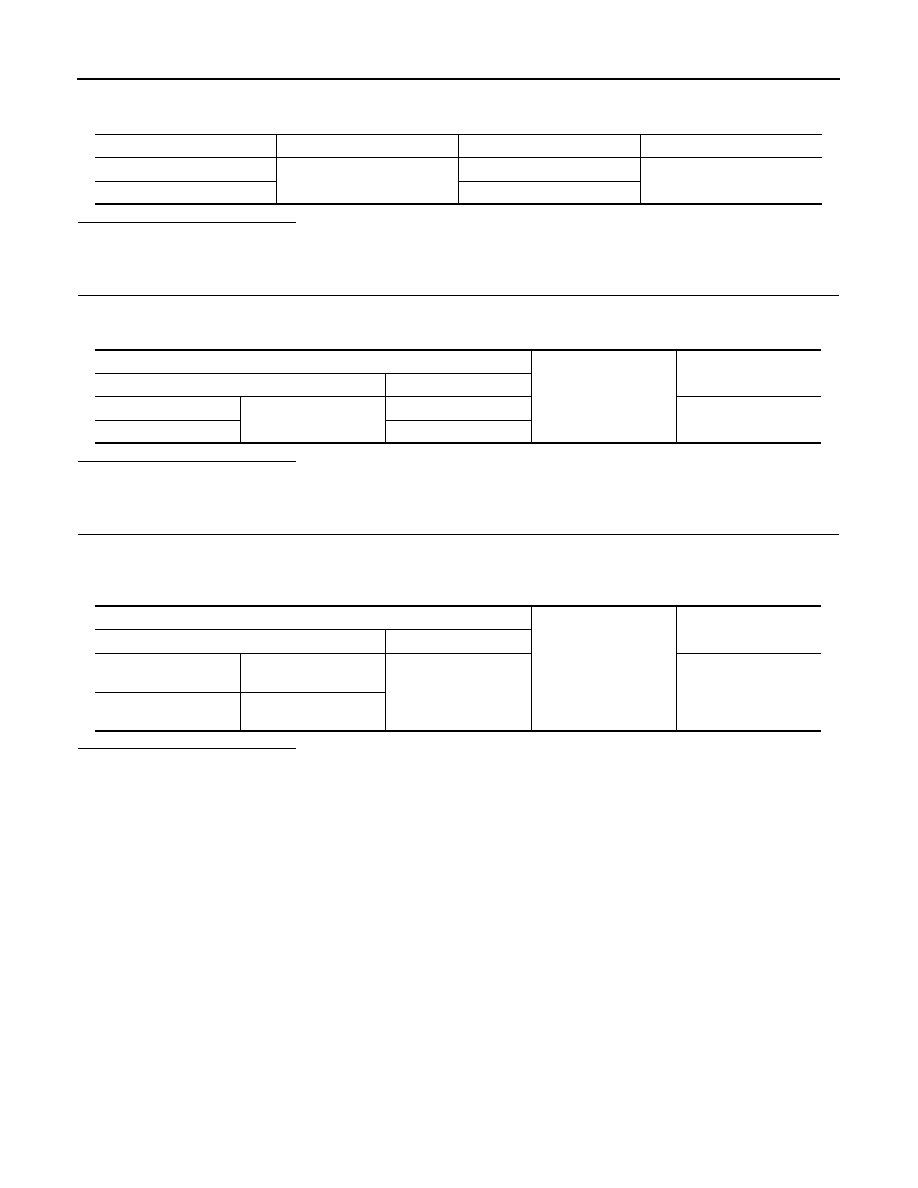
Unit
Lotion
Fuse No.
Capacity
Headlamp LO (RH)
IPDM E/R
#40
15 A
Headlamp LO (LH)
#41
IPDM E/R
Ground
Continuity
Connector
Terminal
RH
E44
16
No
LH
14
Headlamp low
Ground
Continuity
Connector
Terminal
RH
E26 (without DTRL)
E73 (with DTRL)
2
Yes
LH
E25 (without DTRL)
E74 (with DTRL)