Nissan Note E12. Manual - part 215


  Index      Nissan     Nissan Note E12 - Service and Repair Manual


Search            


Content   ..  213  214  215  216   ..


Nissan Note E12. Manual - part 215


P0139 HO2S2

EC-199

< DTC/CIRCUIT DIAGNOSIS >

[HR16DE]

C

D

E

F

G

H

I

J

K

L

M

A

EC

N

P

O

1. Check the continuity between HO2S2 harness connector and ECM harness connector.

2. Check the continuity between HO2S2 harness connector or ECM harness connector and ground.

3. Also check harness for short to power.
Is the inspection result normal?

YES

>> GO TO 5.

NO

>> Repair open circuit or short to ground or short to power in harness or connectors.

5.

CHECK HEATED OXYGEN SENSOR 2

Refer to 

EC-199, "Component Inspection"

.

Is the inspection result normal?

YES

>> Refer to 

GI-41, "Intermittent Incident"

.

NO

>> Replace heated oxygen sensor 2. Refer to 

EX-5, "Exploded View"

.

Component Inspection

INFOID:0000000009582430

1.

INSPECTION START

Do you have CONSULT?

YES

>> GO TO 2.

NO

>> GO TO 3.

2.

CHECK HEATED OXYGEN SENSOR 2

With CONSULT

1. Turn ignition switch ON and select “ENGINE” using CONSULT.

2. Select “DATA MONITOR” mode.

3. Start engine and warm it up to the normal operating temperature.

4. Turn ignition switch OFF and wait at least 10 seconds.

5. Start engine and keep the engine speed between 3,500 and 4,000 rpm for at least 1 minute under no load.

6. Let engine idle for 1 minute.

7. Select “FUEL INJECTION” in “ACTIVE TEST” mode, and select “HO2S2 (B1)” as the monitor item with

CONSULT.

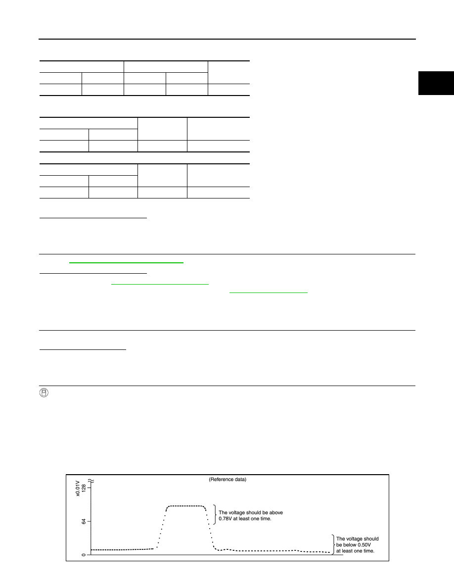
8. Check “HO2S2 (B1)” at idle speed when adjusting “FUEL INJECTION” to 

±25%.

HO2S2

ECM

Continuity

Connector

Terminal

Connector

Terminal

E63

4

F11

50

Existed

HO2S2

Ground

Continuity

Connector

Terminal

E63

4

Ground

Not existed

ECM

Ground

Continuity

Connector

Terminal

F11

50

Ground

Not existed

JSBIA1202GB

EC-200

< DTC/CIRCUIT DIAGNOSIS >

[HR16DE]

P0139 HO2S2

“HO2S2 (B1)” should be above 0.78 V at least once when the “FUEL INJECTION” is +25%.

“HO2S2 (B1)” should be below 0.50 V at least once when the “FUEL INJECTION” is 

25%.

Is the inspection result normal?

YES

>> INSPECTION END

NO

>> GO TO 5.

3.

CHECK HEATED OXYGEN SENSOR 2-I

Without CONSULT

1. Start engine and warm it up to the normal operating temperature.

2. Turn ignition switch OFF and wait at least 10 seconds.

3. Start engine and keep the engine speed between 3,500 and 4,000 rpm for at least 1 minute under no load.

4. Let engine idle for 1 minute.

5. Check the voltage between ECM harness connector terminals under the following condition.

Is the inspection result normal?

YES

>> INSPECTION END

NO

>> GO TO 4.

4.

CHECK HEATED OXYGEN SENSOR 2-II

Check the voltage between ECM harness connector terminals under the following condition.

Is the inspection result normal?

YES

>> INSPECTION END

NO

>> GO TO 5.

5.

CHECK HEATED OXYGEN SENSOR 2-III

Check the voltage between ECM harness connector terminals under the following condition.

Is the inspection result normal?

YES

>> INSPECTION END

NO

>> Replace malfunctioning heated oxygen sensor 2. Refer to 

EX-5, "Exploded View"

.

ECM

Condition

Voltage

Connector

+

Terminal

Terminal

F11

50

(HO2S2)

59

Revving up to 4,000 rpm under no load at 
least 10 times

The voltage should be above 0.78 V at 
least once during this procedure.
The voltage should be below 0.50 V at 
least once during this procedure.

ECM

Condition

Voltage

Connector

+

Terminal

Terminal

F11

50

(HO2S2)

59

Keeping engine at idle for 10 minutes

The voltage should be above 0.78 V at 
least once during this procedure.
The voltage should be below 0.50 V at 
least once during this procedure.

ECM

Condition

Voltage

Connector

+

Terminal

Terminal

F11

50

(HO2S2)

59

Coasting from 80 km/h (50 MPH) in D po-
sition (CVT), 4th gear position (M/T)

The voltage should be above 0.78 V at 
least once during this procedure.
The voltage should be below 0.50 V at 
least once during this procedure.

P0171 FUEL INJECTION SYSTEM FUNCTION

EC-201

< DTC/CIRCUIT DIAGNOSIS >

[HR16DE]

C

D

E

F

G

H

I

J

K

L

M

A

EC

N

P

O

P0171 FUEL INJECTION SYSTEM FUNCTION

DTC Logic

INFOID:0000000009022553

DTC DETECTION LOGIC

With the Air/Fuel Mixture Ratio Self-Learning Control, the actual mixture ratio can be brought closely to the

theoretical mixture ratio based on the mixture ratio feedback signal from the A/F sensor 1. The ECM calcu-

lates the necessary compensation to correct the offset between the actual and the theoretical ratios.

In case the amount of the compensation value is extremely large (The actual mixture ratio is too lean.), the

ECM judges the condition as the fuel injection system malfunction and lights up the MIL (2 trip detection logic).

DTC CONFIRMATION PROCEDURE

1.

PRECONDITIONING

If DTC Confirmation Procedure has been previously conducted, always perform the following procedure

before conducting the next test.

1. Turn ignition switch OFF and wait at least 10 seconds.

2. Turn ignition switch ON.

3. Turn ignition switch OFF and wait at least 10 seconds.

>> GO TO 2.

2.

PERFORM DTC CONFIRMATION PROCEDURE-I

1. Clear the mixture ratio self-learning value. Refer to 

EC-117, "Work Procedure"

.

2. Start engine.
Is it difficult to start engine?

YES

>> GO TO 3.

NO

>> GO TO 4.

3.

RESTART ENGINE

If it is difficult to start engine, the fuel injection system has a malfunction, too.

Crank engine while depressing accelerator pedal.

NOTE:

When depressing accelerator pedal three-fourths (3/4) or more, the control system may not start the engine.

Do not depress accelerator pedal too much.
Does engine start?

YES

>> Proceed to 

EC-202, "Diagnosis Procedure"

.

NO

>> Check exhaust and intake air leak visually.

4.

PERFORM DTC CONFIRMATION PROCEDURE-II

1. Start engine and let it idle for at least 5 minutes.

2. Check 1st trip DTC.
Is 1st trip DTC detected?

YES

>> Proceed to 

EC-202, "Diagnosis Procedure"

.

Sensor

Input signal to ECM

ECM function

Actuator

A/F sensor 1

Density of oxygen in exhaust gas
(Mixture ratio feedback signal)

Fuel injection control

Fuel injector

DTC No.

Trouble diagnosis name

DTC detecting condition

Possible cause

P0171

Fuel injection system too lean

• Fuel injection system does not operate properly.
• The amount of mixture ratio compensation is too 

large. (The mixture ratio is too lean.)

• Intake air leaks
• A/F sensor 1
• Fuel injector
• Exhaust gas leaks
• Incorrect fuel pressure
• Lack of fuel
• Mass air flow sensor
• Incorrect PCV hose connection

EC-202

< DTC/CIRCUIT DIAGNOSIS >

[HR16DE]

P0171 FUEL INJECTION SYSTEM FUNCTION

NO

>> GO TO 5.

5.

PERFORM DTC CONFIRMATION PROCEDURE-III

1. Turn ignition switch OFF and wait at least 10 seconds.

2. Start engine.

3. Maintain the following conditions for at least 10 consecutive minutes.

Hold the accelerator pedal as steady as possible.

CAUTION:

Always drive vehicle at a safe speed.

4. Check 1st trip DTC.
Is 1st trip DTC detected?

YES

>> Proceed to 

EC-202, "Diagnosis Procedure"

.

NO

>> INSPECTION END

Diagnosis Procedure

INFOID:0000000009022554

1.

CHECK EXHAUST GAS LEAK

1. Start engine and run it at idle.

2. Listen for an exhaust gas leak before three way catalyst (manifold).

Is exhaust gas leak detected?

YES

>> Repair or replace.

NO

>> GO TO 2.

2.

CHECK FOR INTAKE AIR LEAK AND PCV HOSE

1. Listen for an intake air leak after the mass air flow sensor.

2. Check PCV hose connection.
Intake air leak detected?

YES

>> Repair or replace.

NO

>> GO TO 3.

3.

CHECK A/F SENSOR 1 INPUT SIGNAL CIRCUIT FOR OPEN AND SHORT

1. Turn ignition switch OFF.

2. Disconnect corresponding A/F sensor 1 harness connector.

3. Disconnect ECM harness connector.

4. Check the continuity between A/F sensor 1 harness connector and ECM harness connector.

5. Check the continuity between A/F sensor 1 harness connector or ECM harness connector and ground.

VHCL SPEED SE

50 - 120 km/h (31 - 75 MPH)

PBIB1216E

A/F sensor 1

ECM

Continuity

Connector

Terminal

Connector

Terminal

F12

1

F11

49

Existed

2

53


Content   ..  213  214  215  216   ..