Nissan Note E12. Manual - part 169


  Index      Nissan     Nissan Note E12 - Service and Repair Manual


Search            


Content   ..  167  168  169  170   ..


Nissan Note E12. Manual - part 169


COMPONENT PARTS

EC-15

< SYSTEM DESCRIPTION >

[HR16DE]

C

D

E

F

G

H

I

J

K

L

M

A

EC

N

P

O

ECM

INFOID:0000000009022416

The ECM consists of a microcomputer and connectors for signal

input and output and for power supply. The ECM controls the engine.

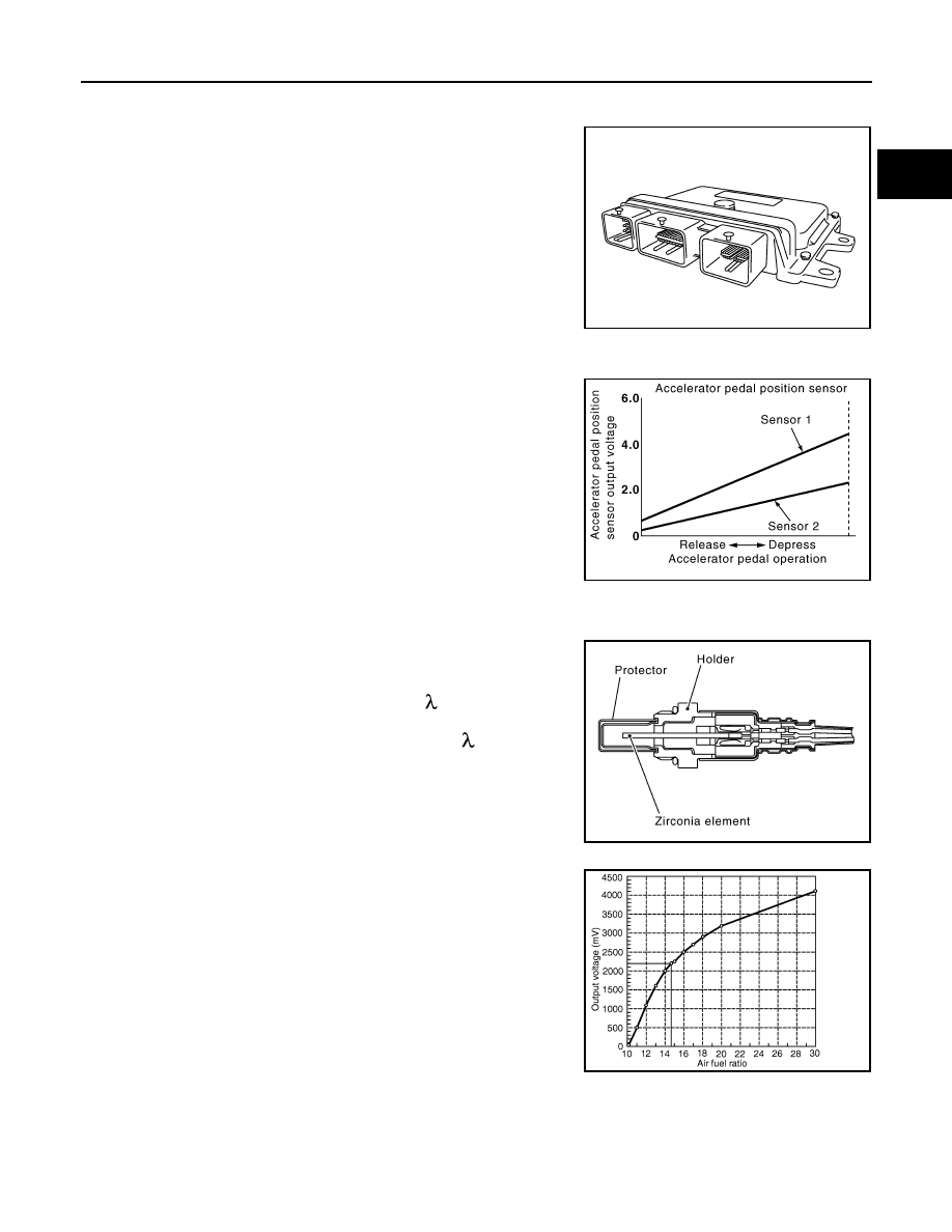
Accelerator Pedal Position Sensor

INFOID:0000000009022417

The accelerator pedal position sensor is installed on the upper end

of the accelerator pedal assembly. The sensor detects the accelera-

tor position and sends a signal to the ECM.

Accelerator pedal position sensor has two sensors. These sensors

are a kind of potentiometer which transform the accelerator pedal

position into output voltage, and emit the voltage signals to the ECM.

The ECM judges the current opening angle of the accelerator pedal

from these signals and controls the throttle control motor based on

these signals.

Idle position of the accelerator pedal is determined by the ECM

receiving the signal from the accelerator pedal position sensor. The

ECM uses this signal for the engine operation such as fuel cut.

Air Fuel Ratio Sensor 1

INFOID:0000000009022418

The air fuel ratio (A/F) sensor 1 is a planar one-cell limit current sen-

sor. The sensor element of the A/F sensor 1 is composed an elec-

trode layer, which transports ions. It has a heater in the element.
The sensor is capable of precise measurement   = 1, but also in the

lean and rich range. Together with its control electronics, the sensor
outputs a clear, continuous signal throughout a wide   range.

The exhaust gas components diffuse through the diffusion layer at

the sensor cell. An electrode layer is applied voltage, and this current

relative oxygen density in lean. Also this current relative hydrocar-

bon density in rich.

Therefore, the A/F sensor 1 is able to indicate air fuel ratio by this

electrode layer of current. In addition, a heater is integrated in the

sensor to ensure the required operating temperature of about 800

°C

(1,472

°F).

Air Fuel Ratio Sensor 1 Heater

INFOID:0000000009022419

SYSTEM DESCRIPTION

PBIA9222J

PBIB1741E

JMBIA0112GB

PBIB3354E

EC-16

< SYSTEM DESCRIPTION >

[HR16DE]

COMPONENT PARTS

The ECM performs ON/OFF duty control of the A/F sensor 1 heater corresponding to the engine operating

condition to keep the temperature of A/F sensor 1 element within the specified range.

ASCD Steering Switch

INFOID:0000000009509471

ASCD steering switch has variant values of electrical resistance for each button. ECM reads voltage variation

of switch, and determines which button is operated.

Refer to 

EC-34, "AUTOMATIC SPEED CONTROL DEVICE (ASCD) : System Description"

 for the ASCD func-

tion.

Camshaft Position Sensor (PHASE)

INFOID:0000000009022421

The camshaft position sensor (PHASE) senses the protrusion of

intake camshaft to identify a particular cylinder. The camshaft posi-

tion sensor (PHASE) senses the piston position.

When the crankshaft position sensor (POS) system becomes inoper-

ative, the camshaft position sensor (PHASE) provides various con-

trols of engine parts instead, utilizing timing of cylinder identification

signals.

The sensor consists of a permanent magnet and Hall IC.

When engine is running, the high and low parts of the teeth cause

the gap with the sensor to change.

The changing gap causes the magnetic field near the sensor to

change.

Due to the changing magnetic field, the voltage from the sensor changes. 

ECM receives the signals as shown in the figure.

Clutch Pedal Position Switch

INFOID:0000000009509475

When the clutch pedal is depressed, the clutch pedal position switch turns OFF and the clutch pedal position

switch signal is sent to the ECM. The ECM judges the clutch pedal conditions via the signal (ON or OFF).

Cooling Fan

INFOID:0000000009022422

Cooling fan operates at low and high speed when the current flows in the cooling fan motor.

Refer to 

EC-35, "COOLING FAN CONTROL : System Description"

 for cooling fan operation.

Sensor

Input Signal to ECM

ECM function

Actuator

Camshaft position sensor (PHASE)
Crankshaft position sensor (POS)

Engine speed

Air fuel ratio (A/F) sensor 1 
heater control

Air fuel ratio (A/F) sensor 1 
heater

Mass air flow sensor

Amount of intake air

PBIA9209J

JPBIA5503GB

COMPONENT PARTS

EC-17

< SYSTEM DESCRIPTION >

[HR16DE]

C

D

E

F

G

H

I

J

K

L

M

A

EC

N

P

O

Crankshaft Position Sensor (POS)

INFOID:0000000009022423

The crankshaft position sensor (POS) is located on the cylinder

block rear housing facing the gear teeth (cogs) of the signal plate at

end of the crankshaft. It detects the fluctuation of the engine revolu-

tion.

The sensor consists of a permanent magnet and Hall IC.

When the engine is running, the high and low parts of the teeth

cause the gap with the sensor to change.

The changing gap causes the magnetic field near the sensor to

change.

Due to the changing magnetic field, the voltage from the sensor

changes.

The ECM receives the voltage signal and detects the fluctuation of

the engine revolution.

ECM receives the signals as shown in the figure.

Electric Throttle Control Actuator

INFOID:0000000009022424

Electric throttle control actuator consists of throttle control motor, throttle position sensor, etc.

The throttle control motor is operated by the ECM and it opens and closes the throttle valve.

The current opening angle of the throttle valve is detected by the throttle position sensor and it provides feed-

back to the ECM to control the throttle valve in response to driving conditions via the throttle control motor.

Engine Coolant Temperature Sensor

INFOID:0000000009022425

The engine coolant temperature sensor is used to detect the engine

coolant temperature. The sensor modifies a voltage signal from the

ECM. The modified signal returns to the ECM as the engine coolant

temperature input. The sensor uses a thermistor which is sensitive to

the change in temperature. The electrical resistance of the ther-

mistor decreases as temperature increases.

<Reference data>

PBIA9209J

JPBIA5503GB

SEF594K

Engine coolant temperature [

°C (°F)]

Voltage* (V)

Resistance (k

Ω)

–10 (14)

4.4

7.0 - 11.4

20 (68)

3.5

2.10 - 2.90

50 (122)

2.2

0.68 - 1.00

90 (194)

0.9

0.236 - 0.260

SEF012P

EC-18

< SYSTEM DESCRIPTION >

[HR16DE]

COMPONENT PARTS

Engine Oil Pressure Sensor

INFOID:0000000009022426

The engine oil pressure (EOP) sensor is detects engine oil pressure

and transmits a voltage signal to the ECM.

Engine Oil Temperature Sensor

INFOID:0000000009022427

The engine oil temperature sensor is used to detect the engine oil

temperature. The sensor modifies a voltage signal from the ECM.

The modified signal returns to the ECM as the engine oil tempera-

ture input. The sensor uses a thermistor which is sensitive to the

change in temperature. The electrical resistance of the thermistor

decreases as temperature increases.

<Reference data>

*: These data are reference values and are measured between ECM terminals.

EVAP Canister Purge Volume Control Solenoid Valve

INFOID:0000000009022428

The EVAP canister purge volume control solenoid valve uses a ON/

OFF duty to control the flow rate of fuel vapor from the EVAP canis-

ter. The EVAP canister purge volume control solenoid valve is

moved by ON/OFF pulses from the ECM. The longer the ON pulse,

the greater the amount of fuel vapor that will flow through the valve.

JSBIA0292ZZ

SEF594K

Engine oil temperature [

°C (°F)]

Voltage

*

 (V)

Resistance (k

Ω)

–10 (14)

4.4

7.0 - 11.4

20 (68)

3.5

2.10 - 2.90

50 (122)

2.2

0.68 - 1.00

90 (194)

0.9

0.236 - 0.260

110 (230)

0.6

0.143 - 0.153

SEF012P

JSBIA0651ZZ


Content   ..  167  168  169  170   ..