Nissan Note E12. Manual - part 141
DLK-68
< DTC/CIRCUIT DIAGNOSIS >
DOOR LOCK ACTUATOR
DOOR LOCK ACTUATOR
DRIVER SIDE
DRIVER SIDE : Component Function Check
INFOID:0000000009515849
1.
CHECK FUNCTION
1. Select DOOR LOCK of BCM using CONSULT.
2. Select DOOR LOCK in ACTIVE TEST mode.
3. Touch ALL LOCK or ALL UNLK to check that it works normally.
Is the inspection result normal?
YES
>> Door lock actuator is OK.
NO
>> Refer to
DLK-68, "DRIVER SIDE : Diagnosis Procedure"
DRIVER SIDE : Diagnosis Procedure
INFOID:0000000009515850
Regarding Wiring Diagram information, refer to
DLK-28, "POWER DOOR LOCK SYSTEM : Wiring Diagram"
.
1.
CHECK DOOR LOCK ACTUATOR INPUT SIGNAL
1. Turn ignition switch OFF.
2. Disconnect front door lock actuator LH connector.
3. Check voltage between front door lock actuator LH harness connector and ground.
Is the inspection result normal?
YES
>> Replace front door lock actuator LH.
NO
>> GO TO 2.
2.
CHECK DOOR LOCK ACTUATOR CIRCUIT
1. Disconnect BCM connector and all door lock actuator connectors.
2. Check continuity between BCM harness connector and front door lock actuator LH harness connector.
3. Check continuity between BCM harness connector and ground.
Is the inspection result normal?
YES
>> GO TO 3.
NO
>> Repair or replace harness.
3.
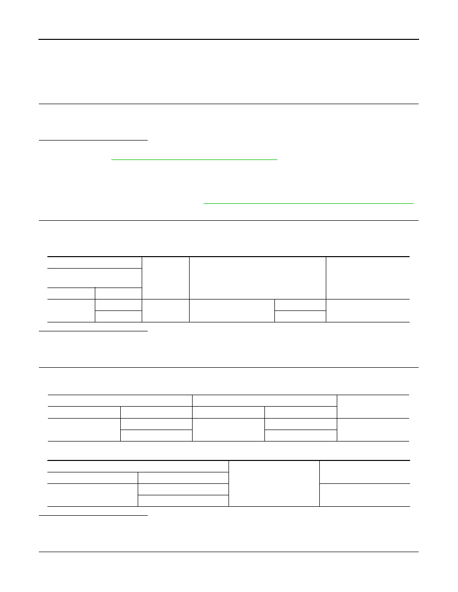
CHECK BCM OUTPUT SIGNAL
1. Connect BCM connector.
2. Check voltage between front door lock actuator LH harness connector and ground.
(+)
(–)
Condition
Voltage
(Approx.)
Front door lock actuator
LH
Connector
Terminal
D14
1
Ground
Door lock and unlock switch
Lock
12 V
2
Unlock
BCM
Front door lock actuator LH
Continuity
Connector
Terminal
Connector
Terminal
M99
66
D14
1
Yes
65
2
BCM
Ground
Continuity
Connector
Terminal
M99
65
No
66