Nissan Note E12. Manual - part 52


  Index      Nissan     Nissan Note E12 - Service and Repair Manual


Search            


Content   ..  50  51  52  53   ..


Nissan Note E12. Manual - part 52


BCS-12

< SYSTEM DESCRIPTION >

SYSTEM

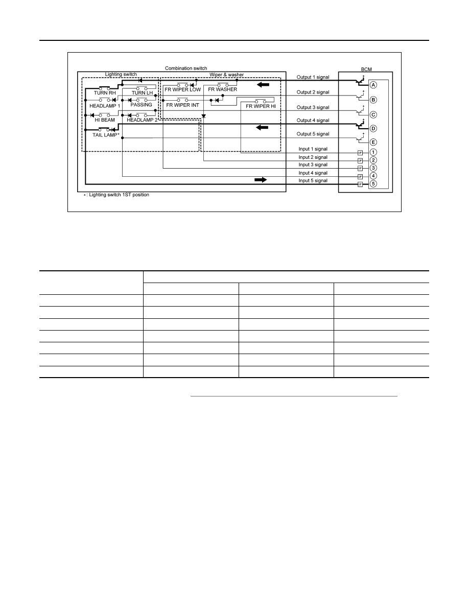
Combination switch circuit (Without Variable Intermittent Wipers)

• BCM detects the combination switch status signal “5AD” when the signals of OUTPUT 1 and OUTPUT 4 are

input to INPUT 5.

• BCM judges that the TURN RH switch and TAIL LAMP switch are ON when the signal “5AD” is detected.

WIPER INTERMITTENT DIAL POSITION (WITH VARIABLE INTERMITTENT WIPERS)

BCM judges the wiper intermittent dial 1 - 7 by the status of INT VOLUME 1, 2 and 3 switches.

NOTE:
For details of wiper intermittent dial position, refer to 

WW-8, "FRONT WIPER AND WASHER SYSTEM : System Description"

.

SIGNAL BUFFER SYSTEM

AWMIA1434GB

Wiper intermittent

dial position

Switch status

INT VOLUME 1

INT VOLUME 2

INT VOLUME 3

1

ON

ON

ON

2

ON

ON

OFF

3

ON

OFF

OFF

4

OFF

OFF

OFF

5

OFF

OFF

ON

6

OFF

ON

ON

7

OFF

ON

OFF

BCS

SYSTEM

BCS-13

< SYSTEM DESCRIPTION >

C

D

E

F

G

H

I

J

K

L

B

A

O

P

N

SIGNAL BUFFER SYSTEM : System Description

INFOID:0000000009567514

SYSTEM DIAGRAM

OUTLINE

BCM has the signal transmission function that outputs/transmits each input/received signal to each unit.

Signal transmission function list

POWER CONSUMPTION CONTROL SYSTEM
POWER CONSUMPTION CONTROL SYSTEM : System Description

INFOID:0000000009567516

SYSTEM DIAGRAM

OUTLINE

• BCM incorporates a power saving control function that reduces the power consumption according to the

vehicle status. 

AWMIA1275GB

Signal name

Input

Output

Description

• Ignition switch ON signal
• Ignition switch signal

Engine switch (push switch)

IPDM E/R (CAN)

Inputs the push-button ignition 
switch (push switch) signal and 
transmits the ignition switch sta-
tus judged with BCM via CAN 
communication.

Door switch signal

Any door switch

• Combination meter (CAN)
• IPDM E/R (CAN)

Inputs the door switch signal 
and transmits it via CAN com-
munication.

ALCIA0030GB

BCS-14

< SYSTEM DESCRIPTION >

SYSTEM

• BCM switches the status (control mode) by itself with the power saving control function. It performs the sleep

request to each unit (IPDM E/R and combination meter) that operates with the ignition switch OFF.

Normal mode (wake-up)

- CAN communication is normally performed with other units

- Each control with BCM is operating properly

CAN communication sleep mode (CAN sleep)

- CAN transmission is stopped

- Control with BCM only is operating

Low power consumption mode (BCM sleep)

- Low power consumption control is active

- CAN transmission is stopped

LOW POWER CONSUMPTION CONTROL WITH BCM

BCM reduces the power consumption with the following operation in the low power consumption mode.

• The reading interval of each switch changes from 10 ms interval to 60 ms interval.

Sleep mode activation

• BCM receives the sleep-ready signal (ready) from IPDM E/R and combination meter via CAN communica-

tion.

• BCM transmits the sleep wake up signal (sleep) to each unit when all of the CAN sleep conditions are ful-

filled.

• Each unit stops the transmission of CAN communication with the sleep wakeup signal. BCM is in CAN com-

munication sleep mode.

• BCM is in the low power consumption mode and performs the low power consumption control when all of the

BCM sleep conditions are fulfilled with CAN sleep condition.

Sleep condition

Wake-up operation

• BCM changes from the low power consumption mode to the CAN communication sleep mode when the any

of the BCM wake-up conditions are fulfilled. Only the control with BCM is activated.

• BCM transmits the sleep wake up signal (wake up) to each unit when any of the CAN wake-up conditions

are fulfilled. It changes from the low power consumption mode or the CAN communication sleep mode to the

normal mode.

• Each unit starts the transmission of CAN communication with the sleep wake up signal. In addition, the com-

bination meter transmits the wake up signal to BCM via CAN communication to report the CAN communica-

tion start.

CAN sleep condition

BCM sleep condition

• Receiving the sleep-ready signal (ready) from all units
• Ignition switch: OFF
• Vehicle security system alarm: No operation
• Warning lamp: Not operation
• Intelligent Key system buzzer: No operation
• Brake switch: OFF
• Turn signal indicator lamp: No operation
• Exterior  lamp:  OFF
• Door lock status: No change
• CONSULT communication status: No communication
• Meter display signal: Non-transmission
• Door switch status: No change
• Rear window defogger: OFF

• Interior room lamp battery saver: Time out
• RAP system: OFF
• Push-button ignition switch (push switch) illumination: OFF
• NATS: No operation
• Remote keyless entry receiver communication status: No com-

munication

BCS

SYSTEM

BCS-15

< SYSTEM DESCRIPTION >

C

D

E

F

G

H

I

J

K

L

B

A

O

P

N

BCM wake-up condition

CAN wake-up condition

• Door lock assembly LH (key cylinder switch): Lock or unlock
• Door lock switch: OFF

→ON

• Door unlock switch: OFF

→ON

• Remote keyless entry receiver: Receiving valid keyfob

• Receiving the sleep-ready signal (Not-ready) from any units
• Push-button ignition switch (push switch): OFF

→ON

• Hazard switch: OFF

→ON

• PASSING switch: OFF

→ON, ON→OFF

• TAIL LAMP switch: OFF

→ON

• Driver door switch: OFF

→ON, ON→OFF

• Passenger door switch: OFF 

→ ON, ON → OFF

• Driver door request switch: OFF

→ON

• Passenger door request switch: OFF

→ON

• Stop lamp switch 2 signal: ON
• Remote keyless entry receiver: Receiving valid keyfob


Content   ..  50  51  52  53   ..