Nissan Rogue. Manual - part 247
DAS
WARNING BUZZER CIRCUIT
DAS-159
< DTC/CIRCUIT DIAGNOSIS >
[DRIVER ASSISTANCE SYSTEM]
C
D
E
F
G
H
I
J
K
L
M
B
N
P
A
WARNING BUZZER CIRCUIT
Component Function Check
INFOID:0000000011277322
1.
CHECK WARNING BUZZER
1. Turn the ignition switch ON.
2. Select “EXTERNAL BUZZER” in “Active Test” of “AVM” using CONSULT.
3. Check the warning system buzzer operation.
Does the warning system buzzer sound?
YES
>> Inspection End.
NO
>> Refer to
DAS-159, "Diagnosis Procedure"
Diagnosis Procedure
INFOID:0000000011277323
Regarding Wiring Diagram information, refer to
.
1.
CHECK WARNING SYSTEM BUZZER POWER SUPPLY CIRCUIT
1. Turn ignition switch OFF.
2. Disconnect warning system buzzer connector.
3. Turn ignition switch ON.
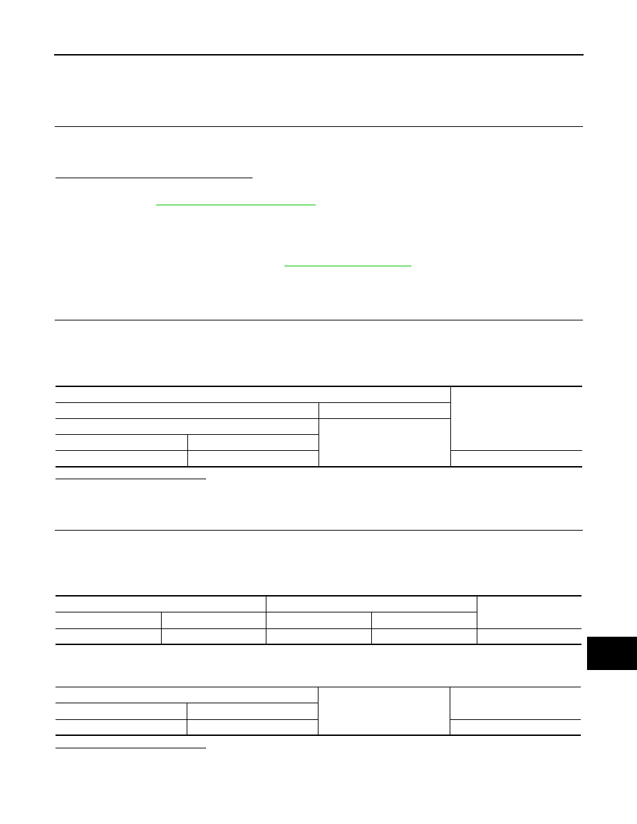
4. Check voltage between warning system buzzer harness connector M120 terminal 1 and ground.
Is the inspection result normal?
YES
>> GO TO 2.
NO
>> Repair the harness or connector.
2.
CHECK WARNING SYSTEM BUZZER CONTROL CIRCUIT
1. Turn ignition switch OFF.
2. Disconnect the around view monitor control unit harness connector M113.
3. Check continuity between the around view monitor control unit harness connector M113 terminal 16 and
warning system buzzer harness connector M120 terminal 2.
4. Check continuity between the around view monitor control unit harness connector M113 terminal 16 and
ground.
Is the inspection result normal?
YES
>> GO TO 3.
NO
>> Repair or replace harness or connector.
Terminals
Voltage
(Approx.)
(+)
(
−)
Warning system buzzer
Ground
Connector
Terminal
M120
1
Battery voltage
Around view monitor control unit
Warning system buzzer
Continuity
Connector
Terminal
Connector
Terminal
M113
16
M120
2
Yes
Around view monitor control unit
Ground
Continuity
Connector
Terminal
M113
16
No