Nissan Rogue. Manual - part 200


  Index      Nissan     Nissan Rogue (2015 year) - Service and Repair Manual


Search            


Content   ..  198  199  200  201   ..


Nissan Rogue. Manual - part 200


CHG-18

< DTC/CIRCUIT DIAGNOSIS >

B TERMINAL CIRCUIT

B TERMINAL CIRCUIT

Description

INFOID:0000000011278228

“B” terminal circuit supplies power to charge the battery and to operate the vehicles electrical system.

Diagnosis Procedure

INFOID:0000000011278229

Regarding Wiring Diagram information. Refer to 

CHG-7, "Wiring Diagram"

.

1.

CHECK “B” TERMINAL CONNECTION

1. Turn ignition switch OFF.

2. Check if “B” terminal is clean and tight.
Is the inspection result normal?

YES

>> GO TO 2.

NO

>> Repair terminal “B” connection. Confirm repair by performing complete Charging system test

using the EXP-800 NI or GR8-1200 NI (if available). Refer to applicable Instruction Manual for

proper testing procedures.

2.

CHECK “B” TERMINAL CIRCUIT

Check voltage between generator “B” terminal and ground.

Is the inspection result normal?

YES

>> GO TO 3.

NO

>> Check harness for open between generator and fusible link.

3.

CHECK “B” TERMINAL CONNECTION (VOLTAGE DROP TEST)

1. Start engine, then engine running at idle and warm.

2. Check voltage between battery positive terminal and generator connector “B” terminal.

Is the inspection result normal?

YES

>> “B” terminal circuit is normal. Refer to 

CHG-11, "Work Flow (With EXP-800 NI or GR8-1200 NI)"

 or

CHG-14, "Work Flow (Without EXP-800 NI or GR8-1200 NI)"

.

NO

>> Check harness between battery and generator for continuity.
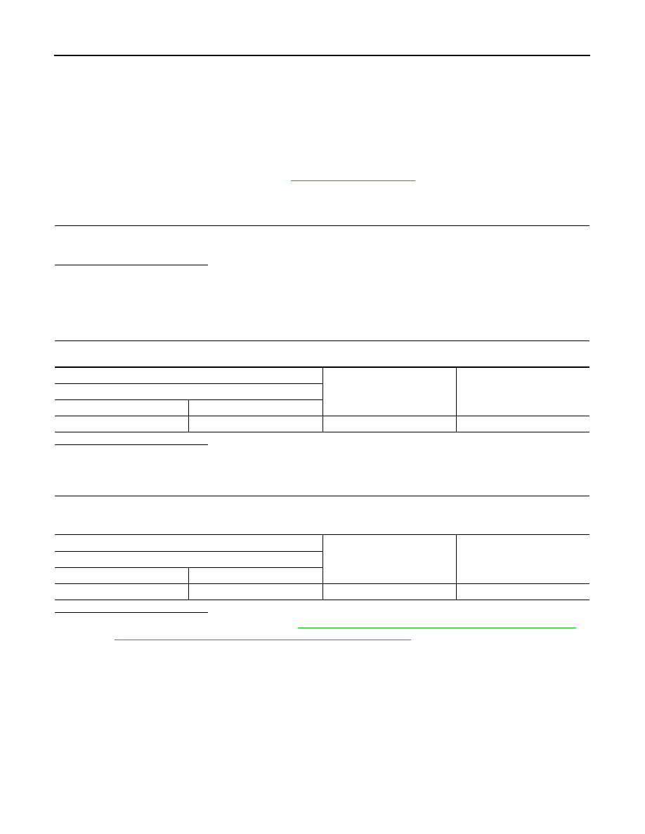
(+)

(-)

Voltage 

(Approx.)

Generator

Connector

Terminal

F29

1

Ground

Battery voltage

(+)

(-)

Voltage 

(Approx.)

Generator

Connector

Terminal

F29

1

Battery positive terminal

Less than 0.2V

CHG

CHARGING SYSTEM

CHG-19

< SYMPTOM DIAGNOSIS >

C

D

E

F

G

H

I

J

K

L

B

A

O

P

N

SYMPTOM DIAGNOSIS

CHARGING SYSTEM

Symptom Table

INFOID:0000000011278230

Symptom

Reference

Battery discharged

Refer to 

CHG-11, "Work Flow (With EXP-800 NI or GR8-1200 NI)"


or 

CHG-14, "Work Flow (Without EXP-800 NI or GR8-1200 NI)"

.

The charge warning lamp does not illuminate when the ignition 
switch is set to ON.

The charge warning lamp does not turn OFF after the engine 
starts.

The charging warning lamp turns ON when increasing the engine 
speed.

CHG-20

< REMOVAL AND INSTALLATION >

GENERATOR

REMOVAL AND INSTALLATION

GENERATOR

Exploded View

INFOID:0000000011278231

REMOVAL

Removal and Installation

INFOID:0000000011278232

REMOVAL

1. Disconnect negative terminal from battery. Refer to 

PG-78, "Exploded View"

.

2. Remove front air spoiler. Refer to 

EXT-28, "FENDER PROTECTOR : Exploded View"

.

3. Remove drive belt. Refer to 

EM-15, "Removal and Installation"

.

4. Remove oil level gauge (1).
5. Remove oil level gauge guide (2).
6. Remove oil level gauge guide O-ring (3).

1.

Generator bracket

2.

"B" terminal harness

3.

Generator

A.

Refer to INSTALLATION

B.

Refer to INSTALLATION

Front

AWMIA1611ZZ

AWMIA1613ZZ

CHG

GENERATOR

CHG-21

< REMOVAL AND INSTALLATION >

C

D

E

F

G

H

I

J

K

L

B

A

O

P

N

7. Disconnect harness connector (A) from the generator.
8. Remove “B” terminal nut (B) and “B” terminal harness.
9. Remove harness bracket (C).

NOTE:

Harness ground does not have to be removed during bracket

removal.

10. Remove upper generator mounting bolt (D), using suitable tool.
11. Remove lower generator mounting bolt (E), using suitable tool.

12. Remove generator upward from the vehicle.
13. Remove generator bracket (if necessary).

INSTALLATION

1. Install generator bracket and tighten bolts in the numerical order

as shown.

2. Install generator and temporarily tighten bolts in the reverse

numerical order as shown.

3. Tighten generator bolts in the numerical order as shown.

4. Installation of remaining components is in the reverse order of removal.
NOTE:

Tighten oil level gauge guide bolt to specification. Refer to 

EM-36, "Exploded View"

.

CAUTION:

• Be careful to tighten “B” terminal nut carefully.

• Install generator and check tension of belt. Refer to 

EM-15, "Checking"

.

• Do not reuse oil level gauge guide O-ring.

• Prior to installation, apply clean engine oil to oil level gauge guide O-ring.

• Ensure O-ring sealing surface is free from dust or imprefections.

• Allow engine to run for 5 minutes and inspect for engine oil leaks. 

Inspection

INFOID:0000000011278233

GENERATOR PULLEY INSPECTION

Perform the following.

• Make sure that the generator pulley does not bind or rattle.

• Make sure that the generator pulley is tight. Refer to 

CHG-20, "Exploded View"

.

AWBIA1830ZZ

JPMIA0752ZZ

Bolts

: 64.7 N·m (6.6 kg-m, 48 ft-lb)

ALMIA0735ZZ

Bolts

: 25 N·m (2.6 kg-m, 18 ft-lb)

ALMIA0736ZZ


Content   ..  198  199  200  201   ..