Nissan Rogue. Manual - part 39
AV-148
< DTC/CIRCUIT DIAGNOSIS >
[NAVIGATION WITHOUT BOSE]
U111C FRONT CAMERA IMAGE SIGNAL CIRCUIT
U111C FRONT CAMERA IMAGE SIGNAL CIRCUIT
DTC Logic
INFOID:0000000011276837
DTC DETECTION LOGIC
Diagnosis Procedure
INFOID:0000000011276838
Regarding Wiring Diagram information, refer to
.
1.
CHECK FRONT CAMERA POWER SUPPLY AND GROUND CIRCUIT CONTINUITY
1. Turn ignition switch OFF.
2. Disconnect around view monitor control unit and front camera connectors.
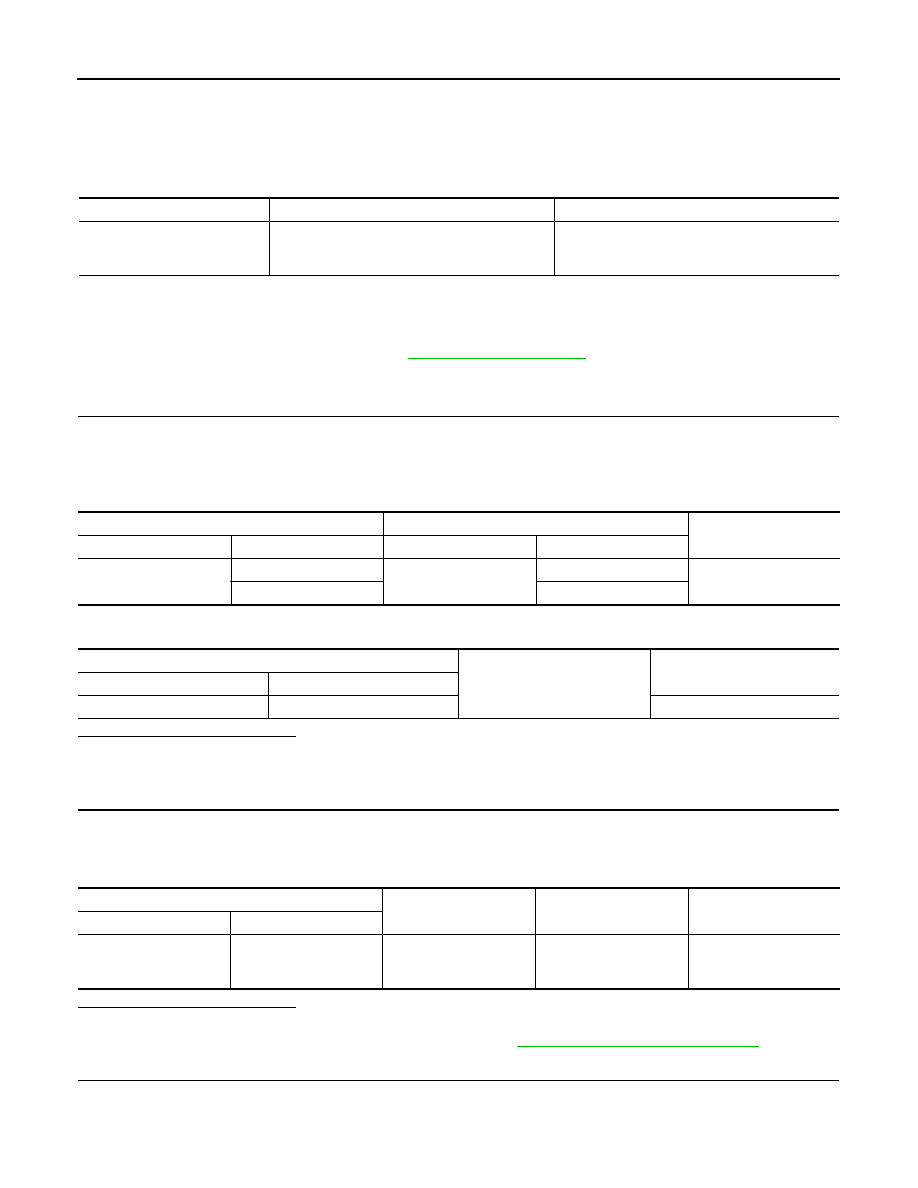
3. Check continuity between around view monitor control unit connector M114 and front camera connector
E226.
4. Check continuity between around view monitor control unit connector M114 and ground.
Is the inspection result normal?
YES
>> GO TO 2.
NO
>> Repair or replace harness or connectors.
2.
CHECK FRONT CAMERA POWER SUPPLY VOLTAGE
1. Connect around view monitor control unit and front camera connectors.
2. Turn ignition switch ON.
3. Check voltage between around view monitor control unit connector M114 and ground.
Is the inspection result normal?
YES
>> GO TO 3.
NO
>> Replace around view monitor control unit. Refer to
AV-208, "Removal and Installation"
3.
CHECK FRONT CAMERA IMAGE SIGNAL AND IMAGE SIGNAL GROUND CIRCUIT CONTINUITY
1. Turn ignition switch OFF.
2. Disconnect around view monitor control unit and front camera connectors.
CONSULT Display
DTC Detection Condition
Possible Cause
Front display output signal diag-
nosis (Harness disconnection)
[U111C]
Front camera image signal circuit open or short.
Check front camera image signal circuit.
Around view monitor control unit
Front camera
Continuity
Connector
Terminals
Connector
Terminals
M114
68
E226
2
Yes
70
1
Around view monitor control unit
Ground
Continuity
Connector
Terminal
M114
68
No
Around view monitor control unit
Ground
Condition
Voltage
(Approx.)
Connector
Terminal
M114
68
—
CAMERA switch is ON or
selector lever in R (re-
verse).
6.0 V