Nissan Maxima. Manual - part 334
DIAGNOSIS SYSTEM (BCM)
DLK-55
< SYSTEM DESCRIPTION >
C
D
E
F
G
H
I
J
L
M
A
B
DLK
N
O
P
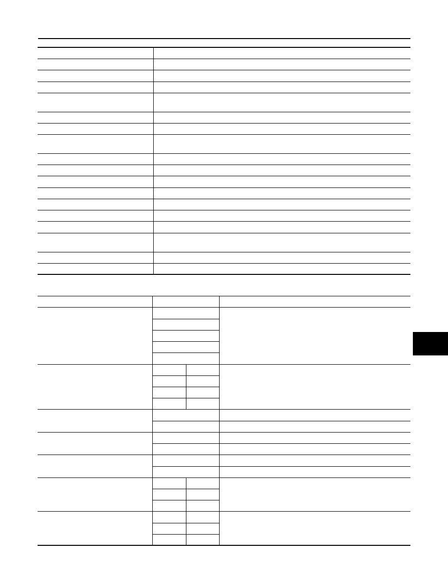
WORK SUPPORT
Test Item
Description
BATTERY SAVER
This test is able to check battery saver operation [On/Off].
PW REMOTO DOWN SET
This test is able to check power window down operation [On/Off].
OUTSIDE BUZZER
This test is able to check Intelligent Key warning buzzer operation [Off/On].
INSIDE BUZZER
This test is able to check combination meter warning chime operation [Key/Knob/Take Out/
Off].
INDICATOR
This test is able to check combination meter warning lamp operation [KEY IND/KEY ON/Off].
INT LAMP
This test is able to check interior room lamp operation [On/Off].
LCD
This test is able to check combination meter display information [Off/LK WN/OUTKEY/NO
KY/BATT/INSRT/SFT P/ROTAT/ID NG/BP I/BP N].
TRUNK/GLASS HATCH
This test is able to check trunk lid opener actuator open operation [Open].
FLASHER
This test is able to check hazard lamp operation [Off/LH/RH].
HORN
This test is able to check horn operation [On].
P RANGE
This test is able to check CVT shift selector illumination operation [On/Off].
ENGINE SW ILLUMI
This test is able to check push button ignition switch illumination operation [On/Off].
LOCK INDICATOR
This test is able to check LOCK indicator in push button ignition switch operation [On/Off].
ACC INDICATOR
This test is able to check ACC indicator in push button ignition switch operation [On/Off].
IGNITION ON IND
This test is able to check ignition ON indicator in push button ignition switch operation [On/
Off].
KEY SLOT ILLUMI
This test is able to check key slot illumination operation [On/Off].
TRUNK/BACK DOOR
This test is able to check trunk lid opener actuator operation [Open].
Support Item
Setting
Description
CONFIRM KEY FOB ID
MEMORY 1
Intelligent Key ID code can be checked.
MEMORY 2
MEMORY 3
MEMORY 4
NON REGIST
AUTO LOCK SET
MODE 4
2 min
Auto door lock time can be set in this mode.
MODE 3
30 sec
MODE 2
5 min
MODE 1*
1 min
LOCK/UNLOCK BY I-KEY
On*
Door lock/unlock function from Intelligent Key ON.
Off
Door lock/unlock function from Intelligent Key OFF.
ENGINE START BY I-KEY
On*
Engine start function from Intelligent Key ON.
Off
Engine start function from Intelligent Key OFF.
TRUNK/GLASS HATCH OPEN
On*
Buzzer reminder function by trunk opener request switch ON.
Off
Buzzer reminder function by trunk opener request switch OFF.
PANIC ALARM SET
MODE 3
1.5 sec
Panic alarm button set time on Intelligent Key can be set in this
mode.
MODE 2
OFF
MODE 1*
0.5 sec
PW DOWN SET
MODE 3
5 sec
Unlock button press time on Intelligent Key to lower front window can
be set in this mode.
MODE 2
OFF
MODE 1*
3 sec