Nissan Maxima. Manual - part 241


  Index      Nissan     Nissan Maxima (2009-2014 year) - Service and Repair Manual


Search            


Content   ..  239  240  241  242   ..


Nissan Maxima. Manual - part 241


BR-32

< REMOVAL AND INSTALLATION >

FRONT DISC BRAKE

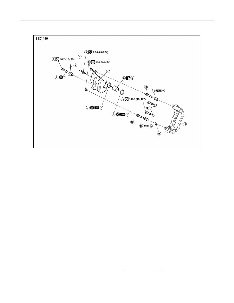
Exploded View of Brake Caliper

INFOID:0000000009466604

Removal and Installation of Brake Caliper and Rotor

INFOID:0000000009466605

WARNING:

Clean dust on caliper and brake pad with a vacuum dust collector to minimize the hazard of air borne

particles or other materials.

CAUTION:

• When removing and installing the cylinder body, do not depress the brake pedal because the piston

will pop out. 

• Do not damage the piston boot.

• Keep the brake rotor free from grease and brake fluid.

• Refill the brake reservoir with new brake fluid only.

• Do not reuse the drained brake fluid.

NOTE:

When removing components such as hoses, tubes/lines, etc., cap or plug openings to prevent fluid from spill-

ing.

REMOVAL

1. Remove front wheel and tire using power tool. Refer to 

WT-60, "Adjustment"

.

2. Secure the disc rotor using a wheel nut.
3. Remove the reservoir cap.

1.

Union bolt

2.

Copper sealing washer

3.

Brake hose

4.

Cap

5.

Bleed valve

6.

Sliding pin bolt

7.

Piston seal

8.

Piston

9.

Piston boot

10. Cylinder body

11. Upper sliding pin

12. Lower sliding pin bolt

13. Torque member bolt

14. Washer

15. Sliding pin boot

16. Bushing

17. Torque member

A.

Rubber grease

B.

Brake fluid

AWFIA0944ZZ

FRONT DISC BRAKE

BR-33

< REMOVAL AND INSTALLATION >

C

D

E

G

H

I

J

K

L

M

A

B

BR

N

O

P

4. Remove the union bolt (1) and disconnect the brake hose from the caliper assembly. Discard the copper

sealing washers.

CAUTION:

Do not reuse copper sealing washers.

5. Remove the upper and lower sliding pin bolts.

NOTE:

Note the sliding pin orientation during removal. The lower sliding pin contains a bushing.

6. Remove the brake caliper.
7. Remove the torque member bolts (2), and the torque member.

CAUTION:

Do not drop the brake pads.

8. Remove the disc rotor. If reusing the disc rotor, apply a matching

mark as shown for installation.

CAUTION:

Put matching marks on wheel hub assembly and disc rotor,

if reusing the disc rotor. 

INSTALLATION

1. Install the disc rotor. If reusing the disc rotor, align the matching

mark on the disc rotor and wheel hub assembly for installation

as shown.

CAUTION:

Align the matching marks on wheel hub assembly and disc

rotor, if reusing the disc rotor. 

2. Install the brake caliper assembly, and tighten the torque member bolts to the specified torque.

CAUTION:

Do not allow oil or any moisture on all contact surfaces between steering knuckle and caliper

assembly, bolts, and washer.

3. Install the brake hose with two new copper sealing washers (1),

using the L-shaped pin for alignment as shown, then tighten the

union bolt (A) to the specified torque.

CAUTION:

Do not reuse copper sealing washers.

4. Refill the brake hydraulic system with new brake fluid and bleed air. Refer to 

BR-16, "Bleeding Brake Sys-

tem"

.

5. Check the front disc brakes for drag.
6. Install the reservoir cap.
7. Install the front wheel and tire. Refer to 

WT-60, "Adjustment"

.

SDIA2608E

SDIA2608E

AWFIA0795ZZ

BR-34

< REMOVAL AND INSTALLATION >

REAR DISC BRAKE

REAR DISC BRAKE

Exploded View of Brake Pads

INFOID:0000000009466606

Removal and Installation of Brake Pads

INFOID:0000000009466607

WARNING:

Clean dust on caliper and brake pad with a vacuum dust collector to minimize the hazard of air borne

particles or other materials.

CAUTION:

• While removing and installing cylinder body, do not depress brake pedal because piston will pop

out.

• It is not necessary to remove bolts on torque member and brake hose except for disassembly or

replacement of caliper assembly. For pad removal and installation, hang cylinder body with a wire so

as not to stretch brake hose.

• Do not damage piston boot.

• If any shim is subject to serious corrosion, replace it with a new one.

• Always replace shim and shim covers as a set when replacing brake pads.

• Keep rotor and pads free from grease and brake fluid.

• Burnish the brake pads and disc rotor mutually contacting surfaces after refinishing or replacing

rotors, after replacing pads, or if a soft pedal occurs at very low mileage. Refer to 

BR-35, "Brake Bur-

nishing Procedure"

.

REMOVAL

1. Partially drain brake fluid from the master cylinder.
2. Remove the rear wheel and tire using power tool. Refer to 

WT-60, "Adjustment"

.

3. Remove the upper sliding pin bolt and loosen the lower sliding pin bolt to swing the cylinder body down.
4. Remove the pads, pad retainers, shims, and shim covers from the torque member.

1.

Inner shim cover

2.

Inner shim

3.

Inner pad

4.

Pad retainer

5.

Outer pad

6.

Outer shim

7.

Outer shim cover

A.

Molykote AS-880N grease

B.

Molykote 7439 grease

AWFIA0945ZZ

REAR DISC BRAKE

BR-35

< REMOVAL AND INSTALLATION >

C

D

E

G

H

I

J

K

L

M

A

B

BR

N

O

P

CAUTION:

Do not deform the pad retainers when removing them from the torque member.

INSTALLATION

1. Apply Molykote AS-880N grease or equivalent to between shim covers and shims. Install inner shim, inner

shim cover to inner pad. Install outer shim and outer shim cover to outer pad.

2. Apply Molykote 7439 grease (A) or equivalent to between pad

retainer and pad. Install pad retainers and pads to torque mem-

ber.

3. Press in piston using suitable tool, until the pads can be

installed, and then install the cylinder body in the torque mem-

ber.

CAUTION:

When replacing pads with new set, check the brake fluid

level in the reservoir tank because brake fluid returns to the

master cylinder reservoir tank when pressing in the piston.

4. Install upper sliding pin bolt and tighten the upper and lower slid-

ing pin bolts to the specified torque.

5. Check the rear disc brakes for drag.
6. Install the rear wheel and tire. Refer to 

WT-60, "Adjustment"

.

7. Check brake fluid level and refill as necessary. Refer to 

BR-16, "Inspection"

.

Brake Burnishing Procedure

INFOID:0000000009466608

Burnish contact surfaces between disc rotors and pads according to following procedure after refinishing or

replacing rotors, after replacing pads, or if a soft pedal occurs at very low mileage.

CAUTION:

• Be careful of vehicle speed because the brake does not operate easily until pad and disc rotor are

securely fitted.

• Only perform this procedure under safe road and traffic conditions. Use extreme caution.

1. Drive vehicle on straight, flat road. 

2. Depress brake pedal with the power to stop vehicle within 3 to 5 seconds until the vehicle stops.

3. Drive without depressing brake for a few minutes to cool the brake.

4. Repeat steps 1 to 3 until pad and disc rotor are securely fitted.

AWFIA0039ZZ


Content   ..  239  240  241  242   ..