Nissan Maxima. Manual - part 236
BR-12
< BASIC INSPECTION >
BRAKE TUBE AND HOSE
BRAKE TUBE AND HOSE
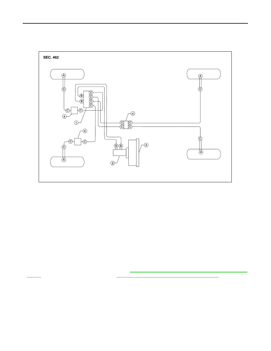
Hydraulic Circuit
INFOID:0000000009466582
CAUTION:
• All hoses and piping (tubes) must be free from excessive bending, twisting and pulling.
• Make sure there is no interference with other parts when turning the steering wheel both clockwise
and counterclockwise.
• The brake piping is an important safety part. If a brake fluid leak is detected, always disassemble the
parts. Replace applicable part with a new one, if necessary.
• Be careful not to splash brake fluid on painted areas; it may cause paint damage. If brake fluid is
splashed on painted areas, wash it away with water immediately.
• Do not bend or twist brake hose sharply, or strongly pull it.
• When removing components, cover connections so that no dirt, dust, or other foreign matter gets in.
• Refill with new specified brake fluid. Refer to
MA-15, "FOR USA AND CANADA : Fluids and Lubri-
(for United States and Canada) or
MA-16, "FOR MEXICO : Fluids and Lubricants"
• Do not reuse drained brake fluid.
FRONT BRAKE
FRONT BRAKE : Inspection
INFOID:0000000009466583
INSPECTION AFTER REMOVAL
CAUTION:
Brake tubes and hoses are important safety parts. Always disassemble the parts and retighten their fit-
tings, if a brake fluid leak is detected. Replace applicable part with a new one, if damaged part is
detected.
1.
Actuator
2.
Master cylinder
3.
Brake booster
4.
Connector
A.
Union bolt
18.2 N·m (1.9 kg-m, 13 ft-lb)
B.
Flare nut M12
22.1 N·m (2.3 kg-m, 16 ft-lb)
C.
Flare nut M10
16.2 N·m (1.7 kg-m, 12 ft-lb)
AWFIA0432ZZ