Nissan Maxima. Manual - part 1205


  Index      Nissan     Nissan Maxima (2009-2014 year) - Service and Repair Manual


Search            


Content   ..  1203  1204  1205  1206   ..


Nissan Maxima. Manual - part 1205


TPMS

WT-9

< SYSTEM DESCRIPTION >

C

D

F

G

H

I

J

K

L

M

A

B

WT

N

O

P

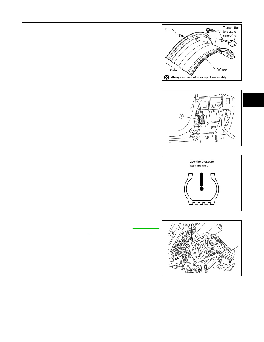
A sensor-transmitter integrated with a valve is installed in each

wheel. It transmits a detected air pressure signal in the form of a

radio wave when the vehicle is moving.  The radio signal is received

by the tire pressure receiver.

TIRE PRESSURE RECEIVER

The tire pressure receiver (1) is located on the RH side of the steer-

ing column, and is shown with the lower instrument panel LH

removed. The tire pressure receiver receives the air pressure signal

transmitted by the transmitter in each wheel.

COMBINATION METER

The combination meter receives tire pressure status from the BCM

using CAN communication. When a low tire pressure condition is

sensed by the BCM, the combination meter low tire pressure warn-

ing lamp is activated. A CHECK TIRE PRESSURE warning mes-

sage will also be displayed in the vehicle information display.  Refer

to the Owner’s Manual for additional information.

TIRE PRESSURE WARNING CHECK CONNECTOR

The tire pressure warning check connector can be grounded in order

to initiate self-diagnosis without a CONSULT. Refer to 

WT-44, "Self-

Diagnosis (Without CONSULT)"

. The tire pressure warning check

connector (1) is located behind the lower portion of the instrument

panel LH, above the hood release handle.

WEIA0137E

AWEIA0123ZZ

LEIA0055E

AWEIA0121ZZ

WT-10

< SYSTEM DESCRIPTION >

TPMS

System Components

INFOID:0000000010046333

AWEIA0150ZZ

1.

Tire pressure receiver M70

2.

BCM M16, M17, M18, M19

3.

Transmitters

4.

Tire pressure warning check connector 
M62

5.

Combination meter M24

DIAGNOSIS SYSTEM (BCM)

WT-11

< SYSTEM DESCRIPTION >

C

D

F

G

H

I

J

K

L

M

A

B

WT

N

O

P

DIAGNOSIS SYSTEM (BCM)

CONSULT Function (BCM - COMMON ITEM)

INFOID:0000000010060544

APPLICATION ITEM

CONSULT performs the following functions via CAN communication with BCM.

SYSTEM APPLICATION

BCM can perform the following functions.

CONSULT Function (BCM - AIR PRESSURE MONITOR)

INFOID:0000000010060545

NOTE:

The Signal Tech II Tool (J-50190) can be used to perform the following functions. Refer to the Signal Tech II

User Guide for additional information.

Direct Diagnostic Mode

Description

Ecu Identification

The BCM part number is displayed.

Self Diagnostic Result

Displays the diagnosis results judged by BCM.

Data Monitor

The BCM input/output signals are displayed.

Active Test

The signals used to activate each device are forcibly supplied from BCM.

Work support

Changes the setting for each system function.

Configuration

• Enables to read and save the vehicle specification.
• Enables to write the vehicle specification when replacing BCM.

CAN Diag Support Mntr

Monitors the reception status of CAN communication viewed from BCM.

System

Sub System

Direct Diagnostic Mode

Ecu Id

en

tificati

on

Sel

f Di

agn

os

tic Re

su

lt

Dat

a

 M

on

ito

r

Acti

ve

 T

est

W

ork

 su

pp

ort

Co

nf

ig

ur

at

io

n

CAN Diag S

upport Mntr

Door lock

DOOR LOCK

×

×

×

×

Rear window defogger

REAR DEFOGGER

×

×

Warning chime

BUZZER

×

×

Interior room lamp timer

INT LAMP

×

×

×

Exterior lamp

HEADLAMP

×

×

×

Wiper and washer

WIPER

×

×

×

Turn signal and hazard warning lamps FLASHER

×

×

×

Intelligent Key system

INTELLIGENT KEY

×

×

×

Combination switch

COMB SW

×

BCM

BCM

×

×

×

×

×

Immobilizer

IMMU

×

×

×

Interior room lamp battery saver

BATTERY SAVER

×

×

×

Trunk open

TRUNK

×

×

Vehicle security system

THEFT ALM

×

×

×

RAP system

RETAINED PWR

×

Signal buffer system

SIGNAL BUFFER

×

×

TPMS

AIR PRESSURE MONITOR

×

×

×

×

WT-12

< SYSTEM DESCRIPTION >

DIAGNOSIS SYSTEM (BCM)

• Activate and display TPMS transmitter IDs

• Display tire pressure reported by the TPMS transmitter

• Read TPMS DTCs

• Register TPMS transmitter IDs

SELF DIAGNOSTIC RESULT

NOTE:

Before performing Self Diagnostic Result, be sure to register the ID, or else the actual malfunction may be dif-

ferent from that displayed on CONSULT.

Refer to 

BCS-64, "DTC Index"

.

DATA MONITOR

ACTIVE TEST

WORK SUPPORT

Monitor Item

Condition

Specification

AIR PRESS FL 

• Drive vehicle for a few minutes.

                           or

• Ignition switch ON and activation tool is trans-

mitting activation signals.

Tire pressure (kPa, kg/cm

2

 or Psi)

AIR PRESS FR

AIR PRESS RR

AIR PRESS RL

ID REGST FL1

Ignition switch ON

Registration ID: Green
No registration: Red

ID REGST FR1

ID REGST RR1

ID REGST RL1

WARNING LAMP

Ignition switch ON

Low tire pressure warning lamp on: ON
Low tire pressure warning lamp off: OFF

BUZZER

Ignition switch ON

Buzzer in combination meter on: ON
Buzzer in combination meter off: OFF

Test Item

Description

WARNING LAMP

This test is able to check tire pressure warning lamp operation [On/Off].

ID REGIST WARNING

This test is able to check ID regist warning chime operation [On/Off].

FLASHER

This test is able to check turn signal lamp operation [Off/LH/RH].

HORN

This test is able to check horn operation [On].

Support Item

Description

ID READ

The registered ID number is displayed.

ID REGIST

Refer to 

WT-6, "ID Registration Procedure"

.


Content   ..  1203  1204  1205  1206   ..