Nissan Altima HL32 Hybrid. Manual - part 596
P0A08-264
HBC-133
< COMPONENT DIAGNOSIS >
D
E
F
G
H
I
J
K
L
M
A
B
HBC
N
O
P
Is DTC detected?
YES
>> Go to the inspection procedure relevant to the output DTC.
NO
>> GO TO 3.
3.
CHECK CONNECTOR CONNECTION CONDITION (HYBRID VEHICLE CONTROL ECU CONNECTOR)
HBC-109, "Diagnosis Procedure"
OK or NG
OK
>> GO TO 4.
NG
>> Connect securely.
4.
CHECK CONNECTOR CONNECTION CONDITION (HV BATTERY CONNECTOR)
HBC-140, "Diagnosis Procedure"
OK or NG
OK
>> GO TO 5.
NG
>> Connect securely.
5.
CHECK HARNESS AND CONNECTOR (RESISTANCE VALUE OF NODD INSIDE HYBRID VEHICLE
CONTROL ECU)
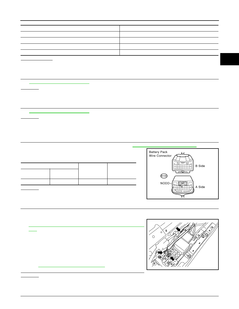
1. Disconnect the HV battery harness connector B130 (See
HBB-97, "Removal and Installation"
).
2. Measure the resistance according to the value(s) in the table
below.
OK or NG
OK
>> GO TO 6.
NG
>> GO TO 12.
6.
CHECK CONNECTOR CONNECTION CONDITION (HV RELAY ASSEMBLY CONNECTOR)
CAUTION:
Be sure to wear insulated gloves.
1. Turn ignition switch OFF and remove the service plug grip (See
HBC-632, "Precautions for Inspecting the Hybrid Control Sys-
NOTE:
After removing the service plug grip, do not Turn ignition switch
to READY position, unless instructed by the repair manual
because this may cause a malfunction.
2. Check the connections of the HV relay assembly connectors.
NOTE:
For the removal procedure of the HV relay assembly connector,
HBB-105, "Removal and Installation"
The connectors are connected securely and there are no contact
problems.
OK
>> GO TO 7.
NG
>> Connect securely.
7.
CHECK HV RELAY ASSEMBLY (HIGH VOLTAGE FUSE)
DTC No.
Relevant Diagnosis
P0A94-547, 548, 549, 550, 124, 125, 126, 127
Boost converter circuit
P0ABC-226, P0ADB-227, P0ADB-229, P0AF0-228
SMR circuit
P3004-131, 803
High-voltage system
P0AE6-225
SMRP circuit
Battery pack wire
Ground
Resistance
Harness
connector
Terminal
B130
6 (NODD)
Ground
120 to 140 k
Ω
JMCIA0177GB
AWCIA0017ZZ