Nissan Altima HL32 Hybrid. Manual - part 142
C1377
BRC-133
< COMPONENT DIAGNOSIS >
[VDC/TCS/ABS]
C
D
E
G
H
I
J
K
L
M
A
B
BRC
N
O
P
3. Measure the voltage according to the value(s) in the table below.
*: For 5 seconds after the driver
′s door is opened.
Is the inspection result normal?
YES
>> GO TO 7.
NO
>> Repair or replace harness or connector (OUT or CTY+ circuit).
7.
RECONFIRM DTC
1. Turn the ignition switch OFF.
2. Clear the DTC.
3. Turn the ignition switch ON.
4. Check if the same DTC is recorded.
Result
A
>> Check for intermittent problems (symptom simulation).
B
>> Replace brake ECU.
8.
CHECK AUXILIARY BATTERY
Check the auxiliary battery voltage.
Is the inspection result normal?
YES
>> GO TO 9.
NO
>> Charge or replace auxiliary battery.
9.
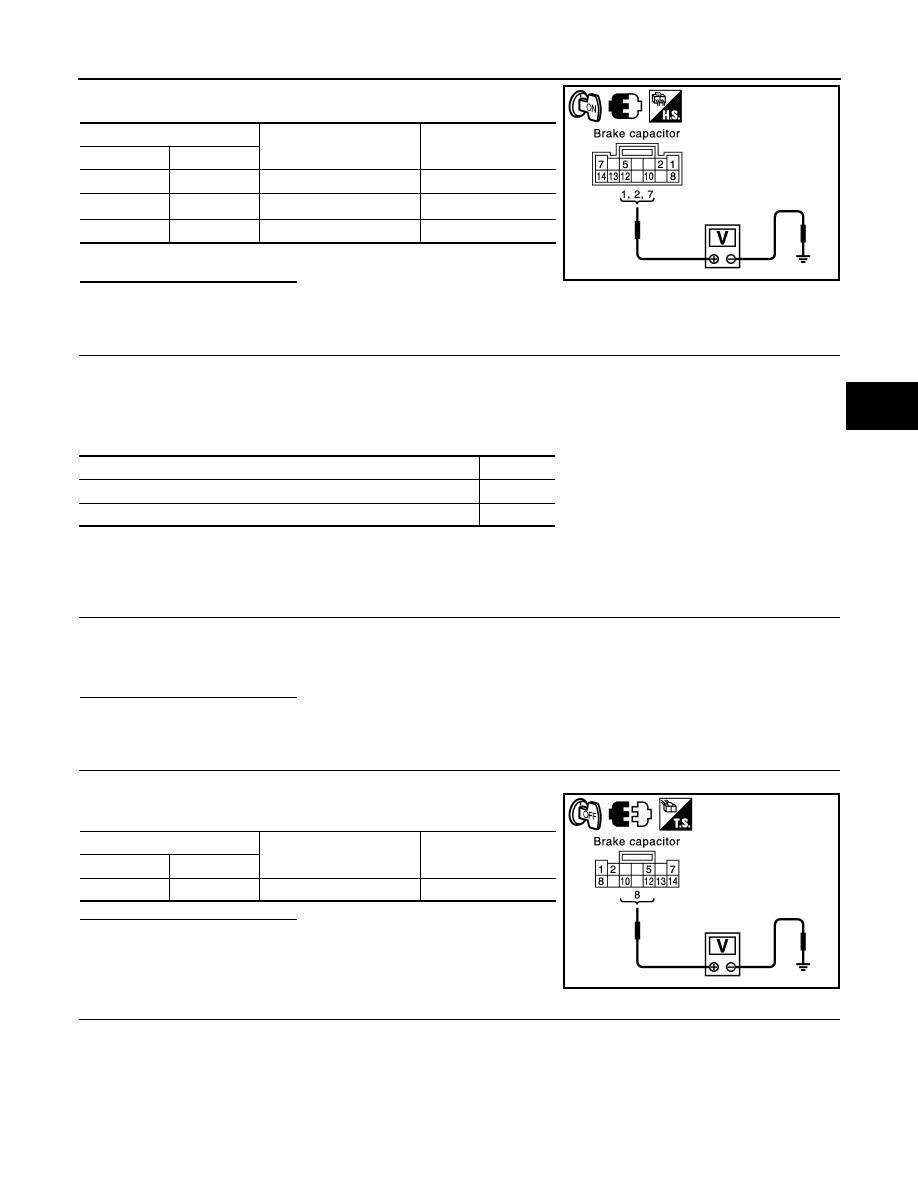
INSPECT BRAKE CAPACITOR (+BC TERMINAL)
1. Disconnect the brake capacitor connector.
2. Measure the voltage according to the value(s) in the table below.
Is the inspection result normal?
YES
>> GO TO 10.
NO
>> Repair or replace harness or connector (+BC circuit).
10.
RECONFIRM DTC
1. Clear the DTC.
2. Turn the ignition switch ON.
3. Check if the same DTC is recorded.
Brake capacitor
Condition
Specified condition
Connector
Terminal
B131
1 – Ground
Always
10 to 14 V
B131
2 – Ground
Always
10 to 14 V
*
B131
7 – Ground
Always
10 to 14 V
JSFIA0369GB
Condition
Proceed to
DTC (C1377) is not output.
A
DTC (C1377) is output.
B
Standard voltage : 11 to 14 V
Brake capacitor
Condition
Specified condition
Connector
Terminal
B131
8 – Ground
Always
10 to 14 V
JSFIA0366GB