Nissan Frontier. Manual - part 758


  Index      Nissan     Nissan Frontier (2014 year) - Service and Repair Manual


Search            


Content   ..  756  757  758  759   ..


Nissan Frontier. Manual - part 758


ENGINE UNIT

EM-221

< UNIT DISASSEMBLY AND ASSEMBLY >

[VQ40DE]

C

D

E

F

G

H

I

J

K

L

M

A

EM

N

P

O

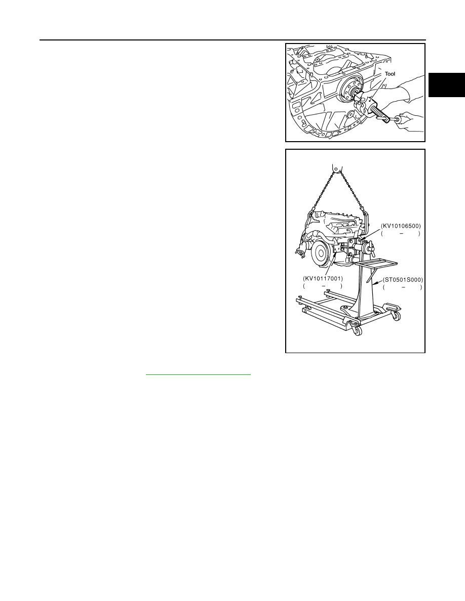
4. Remove pilot converter (A/T models) using Tool as necessary.

5. Lift engine, and mount to engine stand.

CAUTION:

• Use an engine stand that has a load capacity [approxi-

mately 240kg (529 lb) or more] large enough for support-

ing the engine weight. 

• Before removing the hanging chains, make sure the

engine stand is stable and there is no risk of overturning.

6. Drain engine oil. Refer to 

LU-23, "Changing Engine Oil"

.

Tool number

: ST16610001 (J-23907)

WBIA0583E

PBIC0805E

EM-222

< UNIT DISASSEMBLY AND ASSEMBLY >

[VQ40DE]

ENGINE UNIT

7. Drain engine coolant by removing the cylinder block drain plugs

(A), (B), (C) and (D) from cylinder block as shown.

NOTE:

For Canada, (D) is not plug but block heater.

8. Remove cylinder head. Refer to 

EM-205, "Removal and Installation"

.

9. Remove sub harness, and remove knock sensors.

CAUTION:

Handle sensor carefully; do not shock or drop.

10. Remove piston and connecting rod assembly as follows:

• Before removing piston and connecting rod assembly, check the connecting rod side clearance. Refer to

EM-230, "Inspection After Disassembly"

.

CAUTION:

Be careful not to drop connecting rod bearing or scratch the bearing surface.

11. Position crankshaft pin corresponding to connecting rod to be removed onto the bottom dead center.
12. Remove connecting rod bearing cap.
13. Push piston and connecting rod assembly out of the cylinder

head side using suitable tool.

CAUTION:

Be careful not to damage the cylinder wall or crankshaft pin

resulting from an interference of the connecting rod big

end.

14. Remove connecting rod bearings from connecting rod and connecting rod bearing cap.

CAUTION:

Identify installation position, and store them without mixing them up.

15. Remove piston rings from piston.

• Before removing piston rings, check the piston ring side clearance. Refer to 

EM-230, "Inspection After

Disassembly"

.

WLIA0020E

PBIC2940E

ENGINE UNIT

EM-223

< UNIT DISASSEMBLY AND ASSEMBLY >

[VQ40DE]

C

D

E

F

G

H

I

J

K

L

M

A

EM

N

P

O

• Remove piston rings using piston ring expander or suitable

tool.

CAUTION:

• When removing piston rings, be careful not to damage

piston.

• Be careful not to damage piston rings by expanding them

excessively.

16. Remove piston from connecting rod as follows: 
a. Remove snap ring using snap ring pliers.

b. Heat piston to 60

° to 70°C (140° to 158°F) with industrial use

drier or equivalent.

c. Push out piston pin with a drift which has an outer diameter of

approximately 20 mm (0.79 in).

17. Remove lower cylinder block bolts.

• Before loosening lower cylinder block bolts, measure the crankshaft end play. Refer to 

EM-230, "Inspec-

tion After Disassembly"

.

PBIC0087E

PBIC1638E

PBIC1639E

PBIC0262E

EM-224

< UNIT DISASSEMBLY AND ASSEMBLY >

[VQ40DE]

ENGINE UNIT

• Loosen lower cylinder block bolts in reverse order as shown in

several different steps.

NOTE:

Use socket (size E14) for bolts No. 1 to 16 (M10 bolt).

18. Remove lower cylinder block.

• Cut liquid gasket for removal. Refer to 

EM-120, "Precaution for Liquid Gasket"

.

CAUTION:

Be careful not to damage the mounting surfaces.

19. Remove crankshaft.
20. Pull rear oil seal out from rear end of crankshaft.

NOTE:

When replacing rear oil seal without removing lower cylinder block, use a suitable tool to pull the rear oil

seal installed between crankshaft and cylinder block out.

CAUTION:

Be careful not to damage crankshaft or cylinder block.

21. Remove main bearings and thrust bearings from cylinder block and lower cylinder block.

CAUTION:

• Do not drop main bearing, or scratch the surface.

• Identify installation positions, and store them without mixing them up.

22. Remove oil jet.

ASSEMBLY

1. Fully air-blow engine coolant and engine oil passages in cylinder block, cylinder bore and crankcase to

remove any foreign material.

WARNING:

Use goggles to protect your eyes.

PBIC2941E

Tool number

: KV10111100 (J-37228)


Content   ..  756  757  758  759   ..