Nissan Frontier. Manual - part 475
SERVICE DATA AND SPECIFICATIONS (SDS)
EC-471
< SERVICE DATA AND SPECIFICATIONS (SDS)
[QR25DE]
C
D
E
F
G
H
I
J
K
L
M
A
EC
N
P
O
SERVICE DATA AND SPECIFICATIONS (SDS)
SERVICE DATA AND SPECIFICATIONS (SDS)
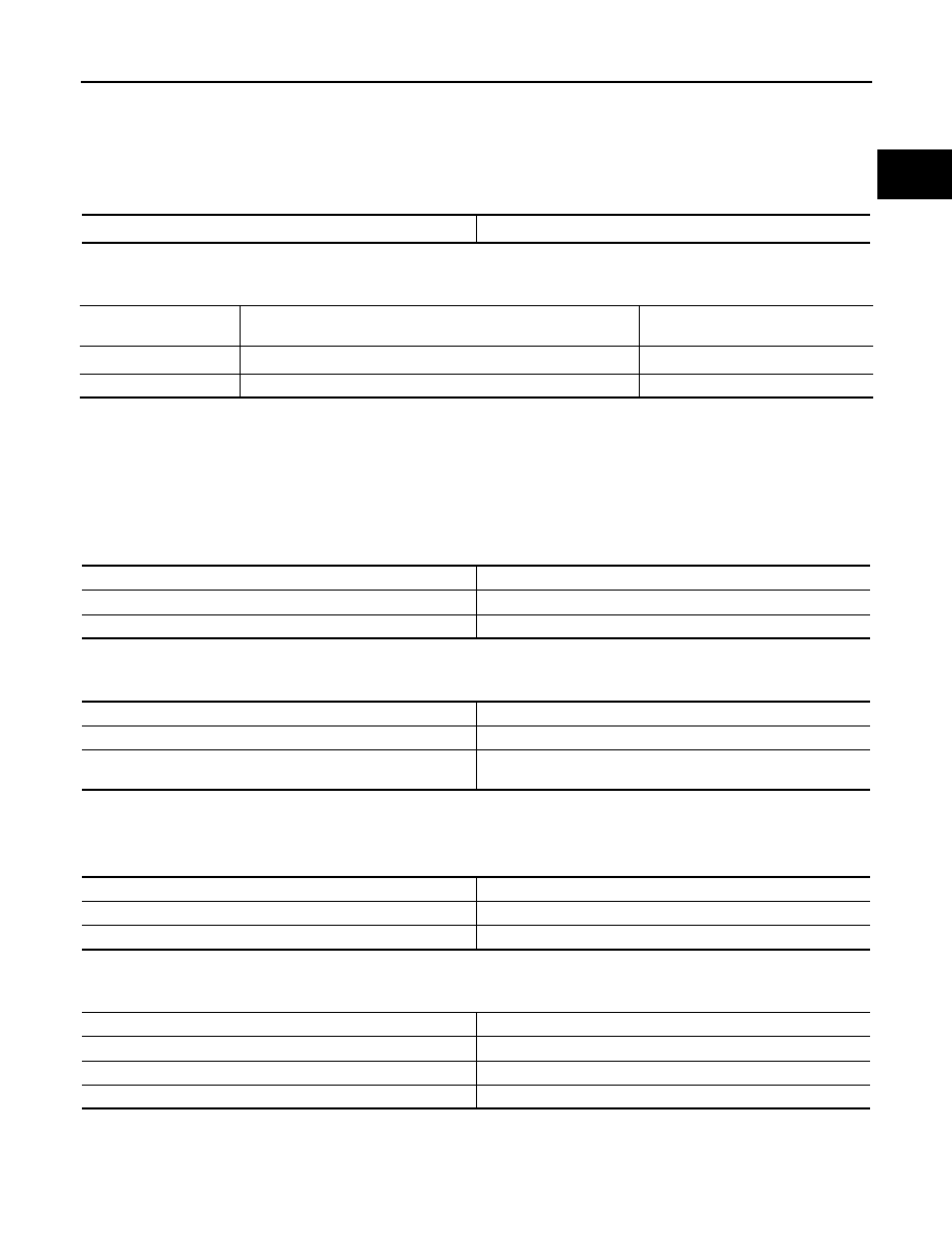
Fuel Pressure
INFOID:0000000009481169
Idle Speed and Ignition Timing
INFOID:0000000009481170
*1: Under the following conditions:
• Air conditioner switch: OFF
• Electric load: OFF (Lights, heater fan)
• Steering wheel: Kept in straight-ahead position
*2: If refrigerant pressure is low, the idle speed may not be increased.
Calculated Load Value
INFOID:0000000009481171
Mass Air Flow Sensor
INFOID:0000000009481172
*: Engine is warmed up to normal operating temperature and running under no load.
Intake Air Temperature Sensor
INFOID:0000000009481173
Engine Coolant Temperature Sensor
INFOID:0000000009481174
Fuel pressure at idle
Approximately 350 kPa (3.57kg/cm
2
, 51psi)
Target idle speed
No load*
1
[in P or N position (A/T) or neutral position (M/T)]
A/T: 700
± 50 rpm
M/T: 625
± 50 rpm
Air conditioner: ON
In P or N position (A/T) or neutral position (M/T)
725 rpm or more*
2
Ignition timing
In P or N position (A/T) or neutral position (M/T)
15
° ± 5° BTDC
Conditions
Calculated load value% (Using CONSULT or GST)
At idle
10 - 35
At 2,500 rpm
10 - 35
Supply voltage
Battery voltage (11 - 14V)
Output voltage at idle
0.9 - 1.2V*
Mass air flow (Using CONSULT or GST)
1.0 - 4.0 g/s at idle*
4.0 - 12.0 g/s at 2,500 rpm*
Temperature
°C (°F)
Resistance k
Ω
25 (77)
1.800 - 2.200
80 (176)
0.283 - 0.359
Temperature
°C (°F)
Resistance k
Ω
20 (68)
2.1 - 2.9
50 (122)
0.68 - 1.00
90 (194)
0.236 - 0.260