Nissan Frontier. Manual - part 245
 

  Index      Nissan     Nissan Frontier (2014 year) - Service and Repair Manual


Search            


Content   ..  243  244  245  246   ..


Nissan Frontier. Manual - part 245


DLK-26

< DTC/CIRCUIT DIAGNOSIS >

POWER SUPPLY AND GROUND CIRCUIT

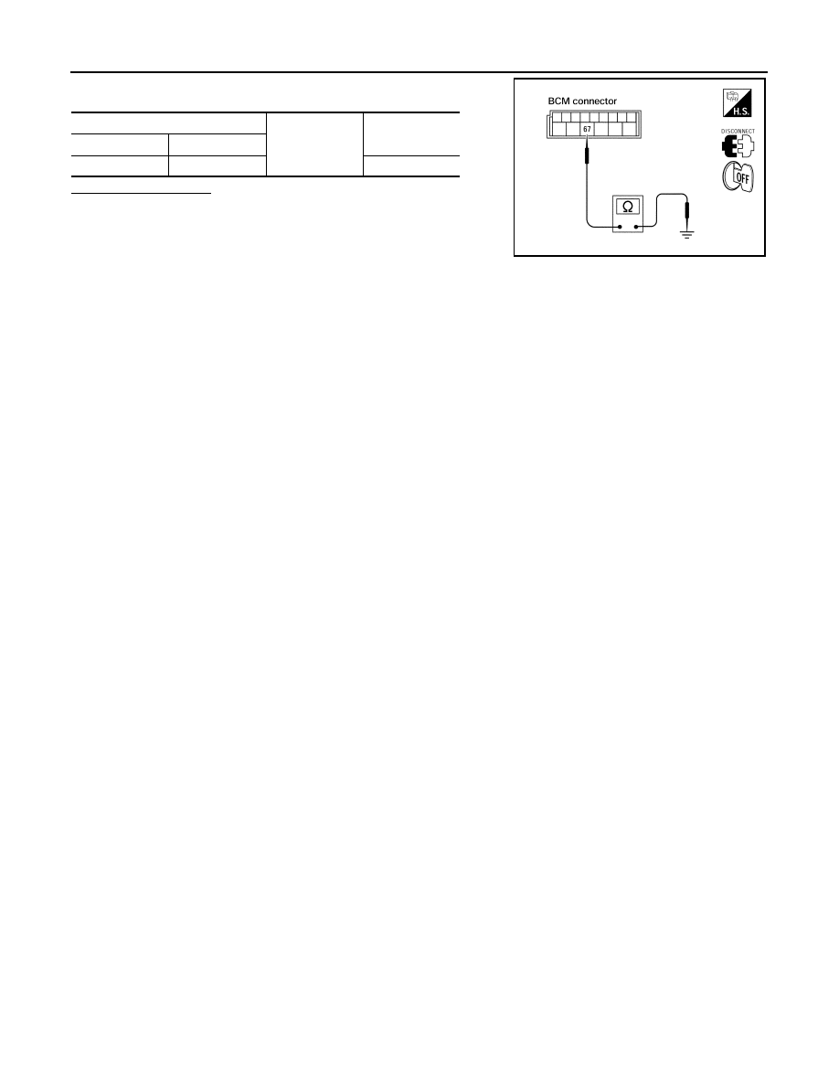
Check continuity between BCM harness connector and ground.

Does continuity exist?

YES

>> Inspection End.

NO

>> Repair or replace harness.

BCM

Ground

Continuity

Connector

Terminal

M20

67

Yes

LIIA0915E

DOOR SWITCH

DLK-27

< DTC/CIRCUIT DIAGNOSIS >

C

D

E

F

G

H

I

J

L

M

A

B

DLK

N

O

P

DOOR SWITCH

KING CAB
KING CAB : Description

INFOID:0000000009478882

Detects door open/close condition.

KING CAB : Component Function Check

INFOID:0000000009478883

1.

CHECK FUNCTION

With CONSULT

Check door switches in Data Monitor mode with CONSULT.

Is the inspection result normal?

YES

>> Door switch is OK.

NO

>> Refer to 

DLK-27, "KING CAB : Diagnosis Procedure"

.

KING CAB : Diagnosis Procedure

INFOID:0000000009478884

Regarding Wiring Diagram information, refer to 

DLK-77, "Wiring Diagram - King Cab"

.

1.

CHECK DOOR SWITCHES INPUT SIGNAL

With CONSULT

Check door switches ("DOOR SW-DR", "DOOR SW-AS") in DATA MONITOR mode with CONSULT. Refer to

BCS-15, "DOOR LOCK : CONSULT Function (BCM - DOOR LOCK)"

.

• When any doors are open:

• When any doors are closed:

Without CONSULT

Check voltage between BCM connector M18 or M19 terminals 12, 47 and ground.

Is the inspection result normal?

YES

>> Door switch circuit is OK.

NO

>> GO TO 2

2.

CHECK BCM OUTPUT VOLTAGE

Monitor item

Condition

DOOR SW-DR

CLOSE 

→ OPEN: OFF → ON

DOOR SW-AS

DOOR SW-DR

:ON

DOOR SW-AS

:ON

DOOR SW-DR

:OFF

DOOR SW-AS

:OFF

Connector

Item

Terminals

Condition

Voltage (V)

(Approx.)

(+)

(–)

M19

Door switches 

LH

47

Ground

Open

Closed

0

Battery voltage

M18

Door switches 

RH

12

LIIA1174E

DLK-28

< DTC/CIRCUIT DIAGNOSIS >

DOOR SWITCH

1. Turn ignition switch OFF.

2. Disconnect door switches.

3. Check voltage between BCM connector M18, M19 terminals 12,

47 and ground.

Is the inspection result normal?

YES

>> GO TO 3

NO

>> Replace BCM. Refer to 

BCS-49, "Removal and Installa-

tion"

.

3.

CHECK DOOR SWITCH CIRCUIT

1. Disconnect BCM.

2. Check continuity between door switch connector D213 (Front LH), D314 (Front RH) terminal 2, D211

(Rear upper LH), D312 (Rear upper RH), D212 (Rear lower LH), D313 (Rear lower RH) terminal 1 and

BCM connector M18, M19 terminals 12, and 47.

3. Check continuity between door switch connector D213 (Front

LH), D314 (Front RH) terminal 2, D211 (Rear upper LH), D312

(Rear upper RH), D212 (Rear lower LH), D313 (Rear lower RH)

terminal 1 and ground.

Is the inspection result normal?

YES

>> GO TO 4

NO

>> Repair or replace harness.

4.

CHECK DOOR SWITCHES GROUND CIRCUIT

Check continuity between door switch connector D213 (Front LH), D314 (Front RH) terminal 3, D211 (Rear

upper LH), D312 (Rear upper RH), D212 (Rear lower LH), D313 (Rear lower RH) terminal 2 and ground.

Is the inspection result normal?

YES

>> GO TO 5

NO

>> Repair or replace harness.

5.

CHECK DOOR SWITCHES

Check continuity between door switch terminals.

12 - Ground

: Battery voltage

47 - Ground

: Battery voltage

LIIA1174E

2 - 47

: Continuity should exist

2 - 12

: Continuity should exist

1 - 47

: Continuity should exist

1 - 12

: Continuity should exist

2 - Ground

: Continuity should not exist

1 - Ground

: Continuity should not exist

LIIA1175E

3 - Ground

: Continuity should exist

2 - Ground

: Continuity should exist

WIIA0715E

DOOR SWITCH

DLK-29

< DTC/CIRCUIT DIAGNOSIS >

C

D

E

F

G

H

I

J

L

M

A

B

DLK

N

O

P

Is the inspection result normal?

YES

>> Check condition of harness and connector.

NO

>> Replace door switch.

CREW CAB
CREW CAB : Description

INFOID:0000000009478885

Detects door open/close condition.

CREW CAB : Component Function Check

INFOID:0000000009478886

1.

CHECK FUNCTION

With CONSULT

Check door switches in Data Monitor mode with CONSULT.

Is the inspection result normal?

YES

>> Door switch is OK.

NO

>> Refer to 

DLK-29, "CREW CAB : Diagnosis Procedure"

.

CREW CAB : Diagnosis Procedure

INFOID:0000000009478887

Regarding Wiring Diagram information, refer to 

DLK-87, "Wiring Diagram - Crew Cab"

.

1.

CHECK DOOR SWITCHES INPUT SIGNAL

With CONSULT

Check door switches ("DOOR SW-DR", "DOOR SW-AS", "DOOR SW-RL", "DOOR SW-RR") in DATA MONI-

TOR mode with CONSULT. Refer to 

BCS-15, "DOOR LOCK : CONSULT Function (BCM - DOOR LOCK)"

.

• When any doors are open:

• When any doors are closed:

Item

Terminal

Condition

Continuity

Door switches 

(front) 

2 – 3 

Open

Yes

Closed

No

Door switches (rear 

upper and lower)

1 – 2 

Open

Yes

Closed

No

WIIA0628E

Monitor item

Condition

DOOR SW-DR

CLOSE 

→ OPEN: OFF → ON

DOOR SW-AS

DOOR SW-RL

DOOR SW-RR

DOOR SW-DR

: ON

DOOR SW-AS

: ON

DOOR SW-RL

: ON

DOOR SW-RR

: ON

DOOR SW-DR

: OFF

DOOR SW-AS

: OFF

DOOR SW-RL

: OFF

DOOR SW-RR

: OFF


Content   ..  243  244  245  246   ..