Nissan Frontier. Manual - part 1274


  Index      Nissan     Nissan Frontier (2014 year) - Service and Repair Manual


Search            


Content   ..  1272  1273  1274  1275   ..


Nissan Frontier. Manual - part 1274


TRANSMISSION ASSEMBLY

TM-307

< UNIT REMOVAL AND INSTALLATION >

[5AT: RE5R05A]

C

E

F

G

H

I

J

K

L

M

A

B

TM

N

O

P

11. Disconnect the A/T fluid cooler tubes from the A/T assembly.

CAUTION:

Do not reuse copper sealing washers.

12. Remove the dust cover from the converter housing.
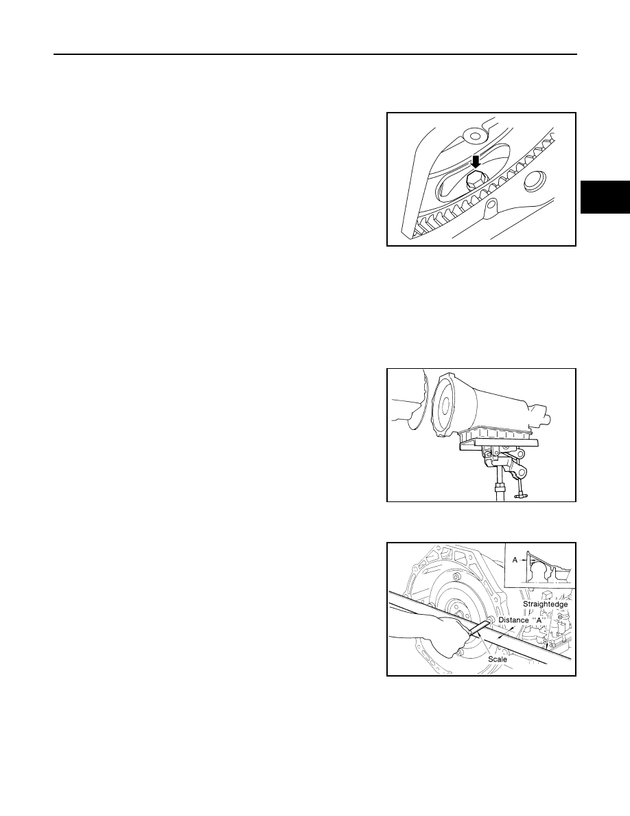
13. Turn the crankshaft to access and remove the four bolts for the

drive plate and torque converter.

CAUTION:

When turning the crankshaft, turn it clockwise as viewed

from the front of the engine.

14. Support the A/T assembly using a transmission jack.

CAUTION:

When setting the transmission jack, be careful not to allow

it to collide against the drain plug.

15. Remove the nuts securing the insulator to the crossmember.
16. Remove the crossmember using power tool.

WARNING:

Support the transmission using suitable jack.

17. Tilt the transmission slightly to gain clearance between the body and the transmission, then disconnect

the air breather hose.

18. Disconnect the A/T assembly harness connector.
19. Remove the harness from the retainers.
20. Remove the A/T fluid indicator pipe.
21. Remove the A/T assembly to engine bolts using power tool.
22. Remove A/T assembly from the vehicle using Tool.

CAUTION:

• Secure the torque converter to prevent it from dropping.

• Secure the A/T assembly to a transmission jack.

NOTE:

The actual special service Tool may differ from Tool shown.

INSPECTION

Installation and Inspection of Torque Converter

• After inserting a torque converter to a transmission, be sure to

check dimension (A) to ensure it is within the reference value limit.

INSTALLATION

Installation of the remaining components is in the reverse order of the removal, while paying attention to the

following.

Tool number

:

 (J-47002)

LCIA0335E

SCIA0499E

Dimension (A)

: 25.0 mm (0.98 in) or more

SAT017B

TM-308

< UNIT REMOVAL AND INSTALLATION >

[5AT: RE5R05A]

TRANSMISSION ASSEMBLY

• When installing the transmission to the engine, install the bolts in

accordance with the standard below.

• Align the positions of bolts for drive plate with those of the torque

converter, and temporarily tighten the bolts. Then, tighten the bolts

with the specified torque.

CAUTION:

• When turning crankshaft, turn it clockwise as viewed from the

front of the engine.

• After converter is installed to drive plate, rotate crankshaft

several turns and check to be sure that transmission rotates

freely without binding.

• When replacing an engine or transmission you must make

sure the dowels are installed correctly during re-assembly.

• Improper alignment caused by missing dowels may cause

vibration, oil leaks or breakage of drive train components.

• After completing installation, check fluid leakage, fluid level, and the positions of A/T. Refer to 

TM-269,

"Checking the A/T Fluid (ATF)"

TM-285, "Inspection and Adjustment"

.

Removal and Installation for VQ40DE 2WD Models

INFOID:0000000009480690

CAUTION:

• Before replacing transmission assembly, perform additional service when replacing transmission

assembly. Refer to 

TM-131, "ADDITIONAL SERVICE WHEN REPLACING TRANSMISSION ASSEMBLY

: Special Repair Requirement"

.

• When removing the A/T assembly from engine, first remove the crankshaft position sensor (POS)

from the A/T assembly.

NOTE:

When removing components such as hoses, tubes/lines, etc., cap or plug openings to prevent fluid from spill-

ing.

REMOVAL

1. Disconnect the negative battery terminal. Refer to 

PG-83, "Removal and Installation"

.

2. Remove the A/T fluid indicator.
3. Remove the front wheel and tire assembly (LH). Refer to 

WT-48, "Adjustment"

.

4. Remove the front mudguard (LH). Refer to 

EXT-29, "Removal and Installation"

.

5. Remove the front fender protector (LH). Refer to 

EXT-27, "Removal and Installation of Front Fender Pro-

tector"

.

6. Remove the crankshaft position sensor (POS) from the A/T

assembly.

CAUTION:

• Do not subject it to impact by dropping or hitting it.

• Do not disassemble.

• Do not allow metal filings or debris to get on the sensor's

front edge magnetic area.

• Do not place in an area affected by magnetism.

7. Remove the under cover(s) using power tool.
8. Remove the front crossmember using power tool.
9. Remove the starter.

Bolt  No.

1

2

3

Quantity

4

1

6

Bolt length “ ”
mm (in)

60

(2.36)

65

(2.56)

Tightening torque
N·m (kg-m, ft-lb)

35

 (3.6, 26)

75

 (7.7, 55)

WCIA0505E

LCIA0335E

LCIA0367E

TRANSMISSION ASSEMBLY

TM-309

< UNIT REMOVAL AND INSTALLATION >

[5AT: RE5R05A]

C

E

F

G

H

I

J

K

L

M

A

B

TM

N

O

P

10. Remove the rear propeller shaft. Refer to 

DLN-163, "Removal and Installation"

 (3S1330), 

DLN-174,

"Removal and Installation"

 (3S1330-2BJ100).

11. Remove the left and right front exhaust tubes. Refer to 

EX-6, "Removal and Installation"

.

12. Remove the shift selector control cable and bracket from the A/T.
13. Disconnect the A/T fluid cooler tubes from the A/T assembly.

CAUTION:

Do not reuse copper sealing washers.

14. Remove the dust cover from the converter housing.
15. Turn the crankshaft to access and remove the four bolts for the

drive plate and torque converter.

CAUTION:

When turning the crankshaft, turn it clockwise as viewed

from the front of the engine.

16. Support the A/T assembly using a transmission jack.

CAUTION:

When setting the transmission jack, be careful not to allow

it to collide against the drain plug.

17. Remove the nuts securing the insulator to the crossmember.
18. Remove the crossmember using power tool.
19. Tilt the transmission slightly to gain clearance between the body and the transmission, then disconnect

the air breather hose.

20. Disconnect the A/T assembly harness connector.
21. Remove the wiring harness from the retainers.
22. Remove the A/T fluid indicator pipe.
23. Remove the A/T assembly to engine bolts using power tool.
24. Remove A/T assembly from the vehicle using Tool.

CAUTION:

• Secure the torque converter to prevent it from dropping.

• Secure the A/T assembly to a transmission jack.

NOTE:

The actual special service Tool may differ from Tool shown.

INSPECTION

Installation and Inspection of Torque Converter

• After inserting a torque converter to a transmission, be sure to

check dimension (A) to ensure it is within the reference value limit.

INSTALLATION

Installation of the remaining components is in the reverse order of the removal, while paying attention to the

following.

Tool number

:

 (J-47002)

LCIA0335E

SCIA0499E

Dimension (A)

: 25.0 mm (0.98 in) or more

SAT017B

TM-310

< UNIT REMOVAL AND INSTALLATION >

[5AT: RE5R05A]

TRANSMISSION ASSEMBLY

• When installing transmission to the engine, tighten the bolts to the

specified torque using sequence shown.

• Align the positions of bolts for drive plate with those of the torque

converter, and temporarily tighten the bolts. Then, tighten the bolts

with the specified torque.

CAUTION:

• When turning crankshaft, turn it clockwise as viewed from the

front of the engine.

• After converter is installed to drive plate, rotate crankshaft

several turns and check to be sure that transmission rotates

freely without binding.

• When replacing an engine or transmission you must make

sure the dowels are installed correctly during re-assembly.

• Improper alignment caused by missing dowels may cause

vibration, oil leaks or breakage of drive train components.

• Install crankshaft position sensor (POS). 

• After completing installation, check fluid leakage, fluid level, and the positions of A/T. Refer to 

TM-269,

"Checking the A/T Fluid (ATF)"

TM-285, "Inspection and Adjustment"

.

Removal and Installation for VQ40DE 4WD Models

INFOID:0000000009480691

CAUTION:

• Before replacing transmission assembly, perform additional service when replacing transmission

assembly. Refer to 

TM-131, "ADDITIONAL SERVICE WHEN REPLACING TRANSMISSION ASSEMBLY

: Special Repair Requirement"

.

• When removing the A/T assembly from engine, first remove the crankshaft position sensor (POS)

from the A/T assembly.

NOTE:

When removing components such as hoses, tubes/lines, etc., cap or plug openings to prevent fluid from spill-

ing.

REMOVAL

1. Disconnect the negative battery terminal. Refer to 

PG-83, "Removal and Installation"

.

2. Remove the A/T fluid indicator.
3. Remove the front wheel and tire assembly (LH). Refer to 

WT-48, "Adjustment"

.

4. Remove the front mudguard (LH). Refer to 

EXT-29, "Removal and Installation"

.

5. Remove the front fender protector (LH). Refer to 

EXT-27, "Removal and Installation of Front Fender Pro-

tector"

.

6. Remove the crankshaft position sensor (POS) from the A/T

assembly.

CAUTION:

• Do not subject it to impact by dropping or hitting it.

• Do not disassemble.

• Do not allow metal filings or debris to get on the sensor's

front edge magnetic area.

• Do not place in an area affected by magnetism.

7. Remove the air dam.
8. Remove the front and rear engine under cover using power tool.
9. Remove the front crossmember using power tool.

Transmission bolts

: 75 N·m (7.6 kg-m, 55 ft-lb)

LCIA0370E

LCIA0335E

LCIA0367E


Content   ..  1272  1273  1274  1275   ..