Nissan Frontier. Manual - part 1205


  Index      Nissan     Nissan Frontier (2014 year) - Service and Repair Manual


Search            


Content   ..  1203  1204  1205  1206   ..


Nissan Frontier. Manual - part 1205


CASE COMPONENTS

TM-31

< UNIT DISASSEMBLY AND ASSEMBLY >

[FS5R30A]

C

E

F

G

H

I

J

K

L

M

A

B

TM

N

O

P

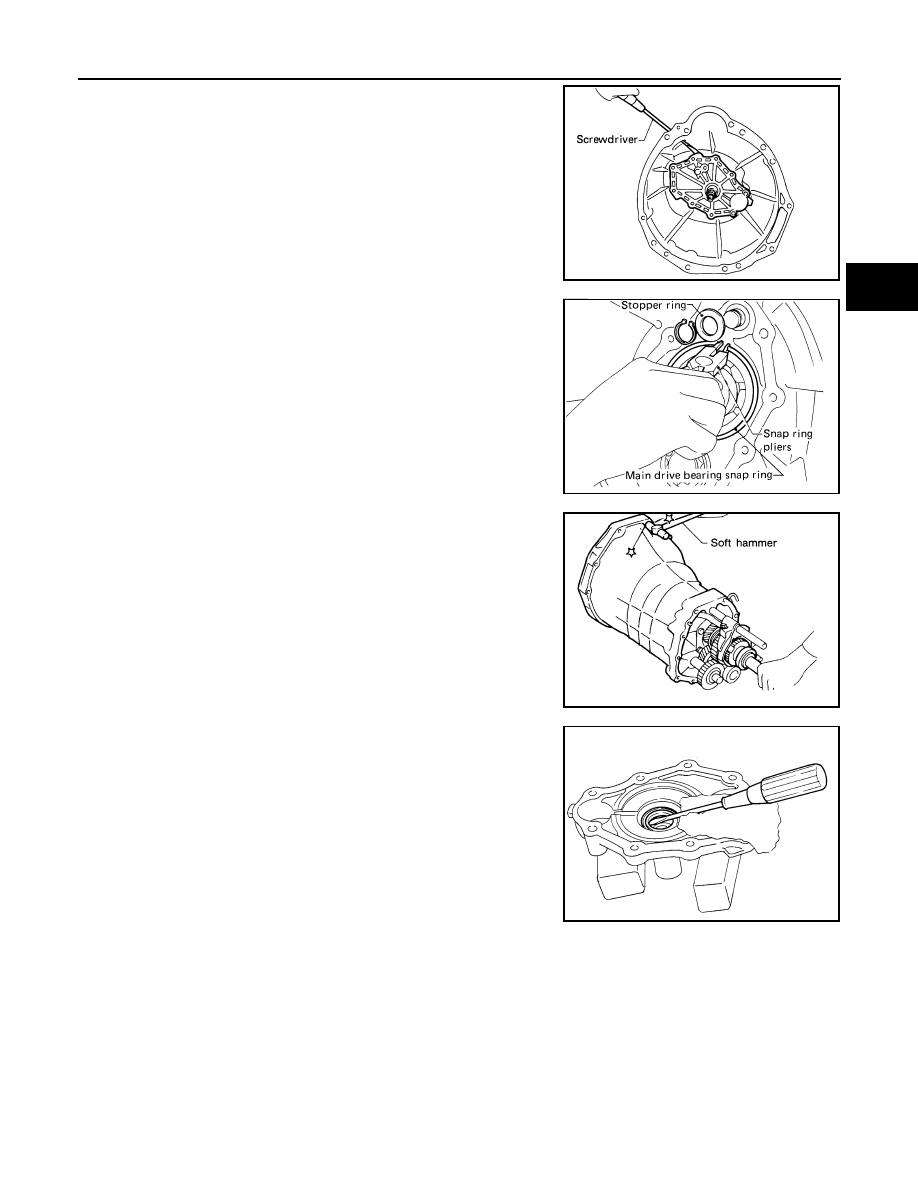
5. Remove front cover and gasket using suitable tool.

6. Remove stopper ring and main drive bearing snap ring using

suitable tool.

7. Remove transmission case by tapping lightly using suitable tool.
8. Remove counter gear front bearing shim and counter gear front

bearing.

9. Remove front cover oil seal using suitable tool.

CAUTION:

Do not damage front cover.

SMT370A

SMT371A

SMT372A

SMT392A

TM-32

< UNIT DISASSEMBLY AND ASSEMBLY >

[FS5R30A]

CASE COMPONENTS

Assembly

INFOID:0000000009480421

1. Install new front cover oil seal using Tool.

CAUTION:

• Apply multi-purpose grease to seal lip.

• Do not reuse front cover oil seal.

2. Install selected counter gear new front bearing shim onto trans-

mission case.

CAUTION:

• Apply multi-purpose grease to counter gear front bearing

shim and counter gear front bearing.

• Do not reuse counter gear front bearing and counter gear front bearing shim.

3. Apply sealant to mating surface of transmission case.

• Use Genuine Silicone RTV or the equivalent. Refer to 

GI-21, "Recommended Chemical Products

and Sealants"

.

4. Install gear assembly onto transmission case.

5. Install interlock stopper to transmission case.
6. Install clip and washer to interlock stopper bolt, and then install

to transmission case. Tighten to the specified torque. 

7. Install stopper ring, new snap ring and new main drive bearing

snap ring using suitable tool.

CAUTION:

Do not reuse the snap rings.

Tool number

: ST33210000 (J-25803-01)

SMT393A

SMT588A

Interlock stopper bolt Refer to 

TM-23, "Overhaul"

PCIB1285E

SMT371A

CASE COMPONENTS

TM-33

< UNIT DISASSEMBLY AND ASSEMBLY >

[FS5R30A]

C

E

F

G

H

I

J

K

L

M

A

B

TM

N

O

P

8. Install front cover and gasket. 

CAUTION:

Do not reuse bolts indicated as (A) shown.

9. Apply sealant to mating surface of adapter plate.

• Use Genuine Silicone RTV or the equivalent. Refer to 

GI-21, "Recommended Chemical Products

and Sealants"

.

10. Install rear extension together with striking arm.

11. Install new retaining pin into striking arm using Tool.

CAUTION:

Do not reuse retaining pin.

12. Install check ball and return spring.
13. Apply sealant to mating surface of rear extension, and then

install control housing.

• Use Genuine Silicone RTV or the equivalent. Refer to 

GI-

21, "Recommended Chemical Products and Sealants"

.

Bolt symbol

Bolt length “ ”

mm (in)

Tightening torque

N·m (kg-m, ft-lb)

(A)

35 (1.38)

16-20 (1.6-2.1, 12-15)

(B)

30 (1.18)

(C)

50 (1.97)

PCIB1288E

Rear extension bolts 

Refer to 

TM-23, "Overhaul"

SMT461A

Tool number

: ST23540000 (J-25689-A)

SMT368A

SMT462A

TM-34

< UNIT DISASSEMBLY AND ASSEMBLY >

[FS5R30A]

CASE COMPONENTS

14. Tighten control housing bolts to the specified torque.

Bolt head size
(A) bolts

: 12 mm (0.47 in)

(B) bolts

: 13 mm (0.51 in)

Control housing bolts

Refer to 

TM-23, "Overhaul"

PCIB1289E


Content   ..  1203  1204  1205  1206   ..