Nissan Frontier. Manual - part 1133


  Index      Nissan     Nissan Frontier (2014 year) - Service and Repair Manual


Search            


Content   ..  1131  1132  1133  1134   ..


Nissan Frontier. Manual - part 1133


KEY CYLINDER SWITCH

SEC-29

< DTC/CIRCUIT DIAGNOSIS >

C

D

E

F

G

H

I

J

L

M

A

B

SEC

N

O

P

Is the inspection result normal?

YES

>> Front door lock assembly LH (key cylinder switch) signal is OK.

NO

>> GO TO 2.

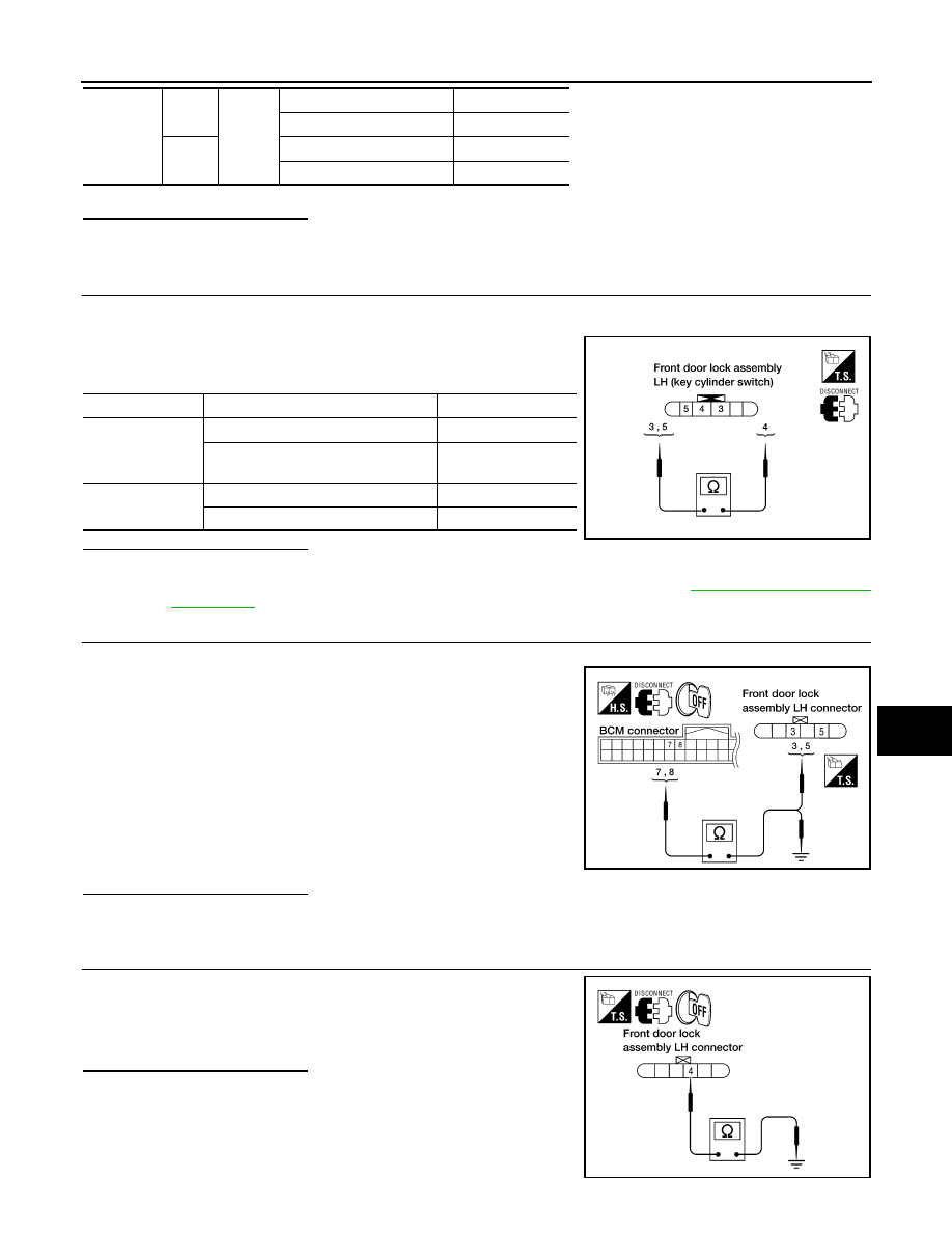
2.

CHECK FRONT DOOR LOCK ASSEMBLY LH (KEY CYLINDER SWITCH)

1. Turn ignition switch OFF.

2. Disconnect front door lock assembly LH (key cylinder switch).

3. Check continuity between front door lock assembly LH (key cyl-

inder switch) connector D14 terminals 3, 4 and 5.

Is the inspection result normal?

YES

>> GO TO 3.

NO

>> Replace front door lock assembly LH (key cylinder switch). Refer to 

DLK-137, "Removal and

Installation"

.

3.

CHECK FRONT DOOR LOCK ASSEMBLY LH HARNESS

1. Disconnect BCM.

2. Check continuity between BCM connector M18 terminals 7, 8

and front door lock assembly LH connector D14 terminals 3, 5.

3. Check continuity between BCM connector M18 terminals 7, 8

and ground.

Is the inspection result normal?

YES

>> GO TO 4.

NO

>> Repair or replace harness.

4.

CHECK FRONT DOOR LOCK ASSEMBLY LH GROUND

Check continuity between front door lock assembly LH connector

D14 terminal 4 and ground.

Is the inspection result normal?

YES

>> GO TO 5.

NO

>> Repair or replace harness.

M18

7

Ground

Neutral/Lock

1.5

Unlock

0

8

Neutral/Unlock

1.5

Lock

0

Terminals

Condition

Continuity

4 – 5

Key is turned to LOCK.

Yes

Key is in N position or turned to UN-

LOCK

No

3 – 4

Key is turned to UNLOCK.

Yes

Key is in N position or turned to LOCK

No

WIIA0458E

7 - 3

: Continuity should exist.

8 - 5

: Continuity should exist.

7 - Ground

: Continuity should not exist.

8 - Ground

: Continuity should not exist.

WIIA0676E

4 - Ground

: Continuity should exist.

WIIA0677E

SEC-30

< DTC/CIRCUIT DIAGNOSIS >

KEY CYLINDER SWITCH

5.

CHECK BCM OUTPUT VOLTAGE

1. Connect BCM.

2. Check voltage between BCM connector M18 terminals 7, 8 and

ground.

Is the inspection result normal?

YES

>> Check condition of the harness and connector.

NO

>> Replace BCM. Refer to 

BCS-49, "Removal and Installa-

tion"

.

7 - Ground

: Approx. 1.5V

8 - Ground

: Approx. 1.5V

WIIA0457E

HORN FUNCTION

SEC-31

< DTC/CIRCUIT DIAGNOSIS >

C

D

E

F

G

H

I

J

L

M

A

B

SEC

N

O

P

HORN FUNCTION

Symptom Table

INFOID:0000000009479057

HAZARD AND HORN REMINDER FUNCTION MALFUNCTION

NOTE:

• Before performing the diagnosis in the following table, check “Work flow”. Refer to 

SEC-3, "Work Flow"

.

• If the following symptoms” are detected, check systems shown in the “Diagnosis/service procedure” column

in this order.

Conditions of Vehicle (Operating Conditions)

• “ANSWER BACK FUNCTION” is ON when setting on CONSULT.

• Ignition switch is in OFF position.

• All doors are closed.

Symptom

Diagnosis/service procedure

Reference 

page

Hazard reminder does not operate by keyfob.
(Horn reminder operate.)

1.

Check “MULTI ANSWER BACK SET” setting in “WORK 
SUPPORT”.

BCS-17

2. Check hazard function.

DLK-56

3. Check keyfob battery inspection.

DLK-51

Horn reminder does not operate by keyfob.
(Hazard reminder operate.)

1.

Check “HORN CHIRP SET” setting in “WORK SUP-
PORT”.

BCS-17

2. Check horn function.

DLK-53

3. Check Intermittent Incident.

GI-42

SEC-32

< DTC/CIRCUIT DIAGNOSIS >

VEHICLE SECURITY INDICATOR

VEHICLE SECURITY INDICATOR

Description

INFOID:0000000009479058

• Vehicle security indicator is built in combination meter.

• NATS (Nissan Anti-Theft System) and vehicle security system conditions are indicated by blink or illumina-

tion of vehicle security indicator.

Component Function Check

INFOID:0000000009479059

1.

CHECK FUNCTION

1. Perform “THEFT IND” in the “Active Test” mode with CONSULT.

2. Check vehicle security indicator operation.

Is the inspection result normal?

YES

>> Inspection End.

NO

>> Refer to 

SEC-32, "Diagnosis Procedure"

.

Diagnosis Procedure

INFOID:0000000009479060

Regarding Wiring Diagram information, refer to 

SEC-52, "Wiring Diagram - King Cab"

 or 

SEC-62, "Wiring Dia-

gram - Crew Cab"

.

1.

CHECK SECURITY INDICATOR LAMP POWER SUPPLY CIRCUIT

1. Turn ignition switch OFF.

2. Disconnect combination meter connector.

3. Check voltage between combination meter harness connector and ground.

Is the inspection result normal?

YES

>> GO TO 2.

NO-1 >> Check 10 A fuse [No. 19, located in the fuse block (J/B)].

NO-2 >> Check harness for open or short between combination meter and fuse.

2.

CHECK SECURITY INDICATOR LAMP SIGNAL

1. Connect combination meter connector.

2. Disconnect BCM connector.

3. Check voltage between BCM harness connector and ground.

Is the inspection result normal?

YES

>> Replace BCM. Refer to 

BCS-49, "Removal and Installation"

.

NO

>> GO TO 3.

Test item

Description

THEFT IND

ON

Vehicle security indicator

ON

OFF

OFF

(+)

(–)

Voltage (V)

Combination meter

Connector

Terminal

M24

3

Ground

Battery voltage

(+)

(–)

Voltage (V)

BCM

Connector

Terminal

M18

23

Ground

Battery voltage


Content   ..  1131  1132  1133  1134   ..