Nissan Frontier. Manual - part 81
 

  Index      Nissan     Nissan Frontier (2014 year) - Service and Repair Manual


Search            


Content   ..  79  80  81  82   ..


Nissan Frontier. Manual - part 81


AV-316

< DTC/CIRCUIT DIAGNOSIS >

[NAVIGATION]

REAR TWEETER

REAR TWEETER

Diagnosis Procedure

INFOID:0000000009482236

Regarding Wiring Diagram information, refer to 

AV-264, "Wiring Diagram"

.

1.

CONNECTOR CHECK

Check the AV control unit, audio amplifier and speaker connectors for the following:

•  Proper connection

•  Damage

•  Disconnected or loose terminals
Is the inspection result normal?

YES

>> GO TO 2

NO

>> Repair the terminals or connectors.

2.

CHECK REAR TWEETER SIGNAL CIRCUIT CONTINUITY

1. Disconnect audio amplifier connector B159 and suspect rear tweeter connector.

2. Check continuity between audio amplifier connector B159 and suspect rear tweeter connector.

3. Check continuity between audio amplifier connector B159 and ground.

Is the inspection result normal?

YES

>> GO TO 3

NO

>> Repair or replace harness or connectors.

3.

CHECK REAR TWEETER SIGNAL

1. Connect audio amplifier connector B159 and suspect rear tweeter connector.

2. Turn ignition switch to ACC.

3. Push AV control unit POWER switch.

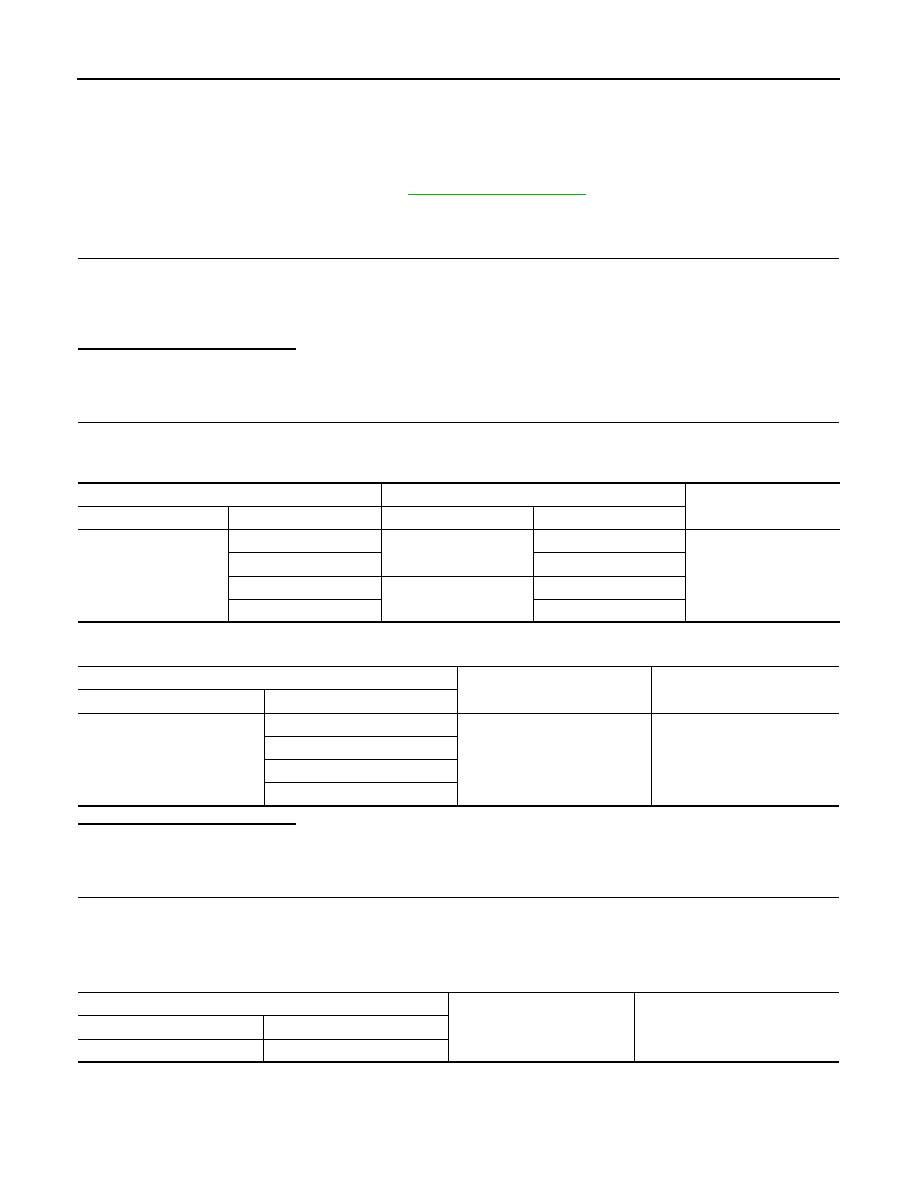
4. Check signal between the terminals of audio amplifier connector B159.

Audio amplifier

Rear tweeter

Continuity

Connector

Terminal

Connector

Terminal

B159

11

D208 (LH)

1

Yes

27

2

12

D308 (RH)

1

28

2

Audio amplifier

Ground

Continuity

Connector

Terminal

B159

11

No

27

12

28

Audio amplifier connector B159

Condition

Reference value

(+)

(

−)

Terminal

Terminal

AV

REAR TWEETER

AV-317

< DTC/CIRCUIT DIAGNOSIS >

[NAVIGATION]

C

D

E

F

G

H

I

J

K

L

M

B

A

O

P

Is the inspection result normal?

YES

>> Replace rear tweeter. Refer to 

AV-353, "Removal and Installation"

.

NO

>> GO TO 4.

4.

CHECK PRE-AMP SIGNAL CIRCUIT CONTINUITY

1. Disconnect AV control unit connector M96 and audio amplifier connector B159.

2. Check continuity between AV control unit connector M96 and audio amplifier connector B159.

3. Check continuity between AV control unit connector M96 and ground.

Is the inspection result normal?

YES

>> GO TO 5.

NO

>> Repair or replace harness or connectors.

5.

CHECK PRE-AMP SIGNAL

1. Connect AV control unit connector M96 and audio amplifier connector B159.

2. Turn ignition switch to ACC.

3. Push AV control unit POWER switch.

4. Check signal between the terminals of AV control unit connector M96.

Is the inspection result normal?

11

27

Audio signal output

12

28

SKIA0177E

AV control unit

Audio amplifier

Continuity

Connector

Terminal

Connector

Terminal

M96

4

B159

24

Yes

5

8

13

23

14

7

AV control unit

Ground

Continuity

Connector

Terminal

M96

4

No

5

13

14

AV control unit connector M96

Condition

Reference value

(+)

(

−)

Terminal

Terminal

4

5

Audio signal output

13

14

SKIA0177E

AV-318

< DTC/CIRCUIT DIAGNOSIS >

[NAVIGATION]

REAR TWEETER

YES

>> Replace audio amplifier. Refer to 

AV-349, "Removal and Installation"

.

NO

>> Replace AV control unit. Refer to 

AV-348, "Removal and Installation"

.

AV

SUBWOOFER

AV-319

< DTC/CIRCUIT DIAGNOSIS >

[NAVIGATION]

C

D

E

F

G

H

I

J

K

L

M

B

A

O

P

SUBWOOFER

Diagnosis Procedure

INFOID:0000000009482237

Regarding Wiring Diagram information, refer to 

AV-264, "Wiring Diagram"

.

1.

CONNECTOR CHECK

Check the AV control unit, audio amplifier and subwoofer connectors for the following:

•  Proper connection

•  Damage

•  Disconnected or loose terminals
Is the inspection result normal?

YES

>> GO TO 2

NO

>> Repair the terminals or connectors.

2.

CHECK SUBWOOFER SIGNAL CIRCUIT CONTINUITY

1. Disconnect audio amplifier connector B158 and subwoofer connector.

2. Check continuity between audio amplifier connector B158 and subwoofer connector.

3. Check continuity between audio amplifier connector B158 and ground.

Is the inspection result normal?

YES

>> GO TO 3

NO

>> Repair or replace harness or connectors.

3.

CHECK SUBWOOFER SIGNAL

1. Connect audio amplifier connector B158 and subwoofer connector.

2. Turn ignition switch to ACC.

3. Push AV control unit POWER switch.

4. Check signal between the terminals of audio amplifier connector B158.

Audio amplifier

Subwoofer

Continuity

Connector

Terminal

Connector

Terminal

B158

2

B72

1

Yes

18

2

3

3

19

4

Audio amplifier

Ground

Continuity

Connector

Terminal

B158

2

No

18

3

19

Audio amplifier connector B158

Condition

Reference value

(+)

(

−)

Terminal

Terminal


Content   ..  79  80  81  82   ..