Nissan Sentra. Manual - part 713


  Index      Nissan     Nissan Sentra (2014 year) - Service and Repair Manual


Search            


Content   ..  711  712  713  714   ..


Nissan Sentra. Manual - part 713


POWER WINDOW MOTOR

PWC-49

< DTC/CIRCUIT DIAGNOSIS >

C

D

E

F

G

H

I

J

L

M

A

B

PWC

N

O

P

Is the inspection result normal?

YES

>> Check rear power window switch RH. Refer to 

PWC-49, "REAR RH : Component Inspection"

.

NO

>> Repair or replace harness or connectors.

3.

 CHECK REAR POWER WINDOW MOTOR RH

Check rear power window motor RH.

Refer to 

PWC-49, "REAR RH : Component Inspection"

.

Is the inspection result normal?

YES

>> Check intermittent incident. Refer to 

GI-39, "Intermittent Incident"

.

NO

>> Replace rear power window motor RH. Refer to 

GW-21, "Removal and Installation"

.

REAR RH : Component Inspection

INFOID:0000000009757263

COMPONENT INSPECTION

1.

 CHECK REAR POWER WINDOW MOTOR RH

Check motor operation by connecting the battery voltage directly to rear power window motor RH D304.

Is the inspection result normal?

YES

>> Power window motor is OK.

NO

>> Replace rear power window motor RH. Refer to 

GW-21, "Removal and Installation"

.

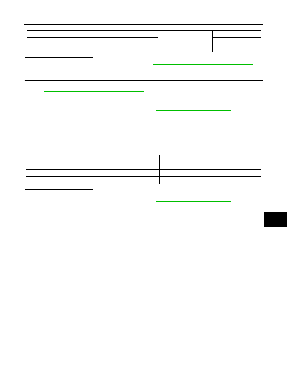
Rear power window switch RH connector

Terminal

Ground

Continuity

D303

5

No

8

Terminal

Motor condition

(+)

(–)

3

1

DOWN

1

3

UP

PWC-50

< DTC/CIRCUIT DIAGNOSIS >

ENCODER

ENCODER

DRIVER SIDE
DRIVER SIDE : Description

INFOID:0000000009757264

Detects condition of the front power window motor LH operation and transmits to main power window and door

lock/unlock switch as pulse signal. 

DRIVER SIDE : Component Function Check

INFOID:0000000009757265

1.

 CHECK ENCODER OPERATION

Check front door glass LH perform AUTO open/close operation normally with main power window and door

lock/unlock switch.
Is the inspection result normal?

YES

>> Encoder operation is OK.

NO

>> Refer to 

PWC-50, "DRIVER SIDE : Diagnosis Procedure"

.

DRIVER SIDE : Diagnosis Procedure

INFOID:0000000009757266

Regarding Wiring Diagram information, refer to 

PWC-18, "Wiring Diagram"

.

Encoder Circuit Check

1.

 CHECK ENCODER OPERATION

1. Connect front power window motor LH.

2. Turn ignition switch ON.

3. Check signal between main power window and door lock/unlock switch connector D5 and ground with

oscilloscope.

Is the inspection result normal?

YES

>> Check intermittent incident. Refer to 

GI-39, "Intermittent Incident"

.

NO

>> GO TO 2.

2.

 CHECK FRONT POWER WINDOW MOTOR LH POWER SUPPLY

1. Turn ignition switch ON.

2. Check voltage between front power window motor LH connector D8 and ground.

Terminals

Signal

(Reference value)

(+)

(–)

 Main power window and door lock/

unlock switch 

connector

Terminal 

D5

4

Ground

Refer to following signal

5

JMKIA5210GB

ENCODER

PWC-51

< DTC/CIRCUIT DIAGNOSIS >

C

D

E

F

G

H

I

J

L

M

A

B

PWC

N

O

P

Is the inspection result normal?

YES

>> GO TO 4.

NO

>> GO TO 3.

3.

 CHECK HARNESS CONTINUITY 1

1. Turn ignition switch OFF.

2. Disconnect main power window and door lock/unlock switch and front power window motor LH.

3. Check continuity between main power window and door lock/unlock switch connector D5 and front power

window motor connector D8.

4. Check continuity between main power window and door lock/unlock switch connector D5 and ground.

Is the inspection result normal?

YES

>> Replace main power window and door lock/unlock switch. Refer to 

PWC-70, "Removal and Instal-

lation"

. After that, refer to 

PWC-29, "Work Procedure"

.

NO

>> Repair or replace harness or connectors.

4.

 CHECK GROUND CIRCUIT

1. Turn ignition switch OFF.

2. Disconnect front power window motor LH.

3. Check continuity between front power window motor LH connector D8 and ground.

Is the inspection result normal?

YES

>> GO TO 6.

NO

>> GO TO 5.

5.

 CHECK HARNESS CONTINUITY 2

1. Disconnect main power window and door lock/unlock switch.

2. Check continuity between main power window and door lock/unlock switch connector D5 and front power

window motor LH connector D8.

Is the inspection result normal?

YES

>> Check main power window and door lock/unlock switch. Refer to 

PWC-36, "POWER WINDOW

MAIN SWITCH : Component Inspection"

.

NO

>> Repair or replace the harness or connectors.

6.

 CHECK HARNESS CONTINUITY 3

1. Disconnect main power window and door lock/unlock switch.

Terminal

Voltage

(Approx.)

(+)

(–)

 Front power window motor LH connector

Terminal 

D8

2

Ground

Battery voltage

Main power window and door lock/

unlock switch connector

Terminal

Front power window motor LH 

connector

Terminal

Continuity

D5

14

D8

2

Yes

Main power window and door lock/unlock switch con-

nector

Terminal

Ground

Continuity

D5

14

No

Front power window motor LH connector

Terminal

Ground

Continuity 

D8

6

Yes

Main power window and door lock/un-

lock switch connector

Terminal

Front power window motor LH 

connector

Terminal

Continuity

D5

12

D8

6

Yes

PWC-52

< DTC/CIRCUIT DIAGNOSIS >

ENCODER

2. Check continuity between main power window D5 and door lock/unlock switch connector and front power

window motor LH connector D8.

3. Check continuity between main power window and door lock/unlock switch connector D5 and ground.

Is the inspection result normal?

YES

>> Replace front power window motor LH. Refer to 

GW-16, "Removal and Installation"

. After that,

refer to 

PWC-29, "Work Procedure"

.

NO

>> Repair or replace harness or connectors. 

DRIVER SIDE : Special Repair Requirement

INFOID:0000000009757267

1.

 PERFORM INITIALIZATION PROCEDURE

Perform initialization procedure. 

Refer to 

PWC-29, "Work Procedure"

.

Is the inspection result normal?

YES

>> Inspection end.

NO

>> Check intermittent incident. Refer to 

GI-39, "Intermittent Incident"

.

Main power window and door lock/unlock 

switch connector

Terminal

Front power window motor 

LH connector

Terminal

Continuity

D5

4

D8

5

Yes

5

4

Main power window and door lock/unlock 

switch connector

Terminal

Ground

Continuity

D5

4

No

5


Content   ..  711  712  713  714   ..