Nissan Sentra. Manual - part 496
FL-6
< REMOVAL AND INSTALLATION >
FUEL LEVEL SENSOR UNIT, FUEL FILTER AND FUEL PUMP ASSEMBLY
REMOVAL AND INSTALLATION
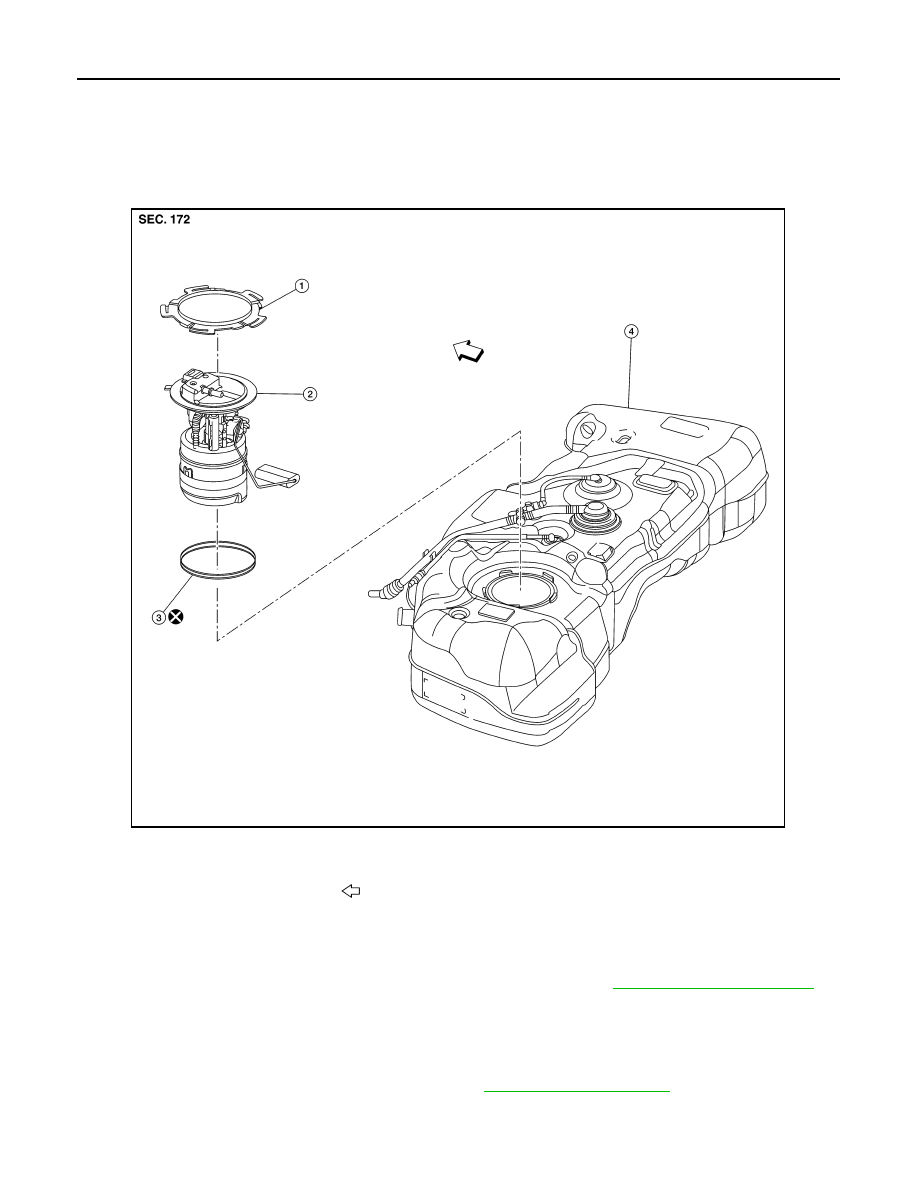
FUEL LEVEL SENSOR UNIT, FUEL FILTER AND FUEL PUMP ASSEMBLY
Exploded View
INFOID:0000000009756227
Removal and Installation
INFOID:0000000009756228
WARNING:
Read “General Precautions” when working on the fuel system. Refer to
NOTE:
When removing components such as hoses, tubes/lines, etc., cap or plug openings to prevent fluid from spill-
ing.
REMOVAL
1. Release the fuel pressure from the fuel lines. Refer to
.
1.
Lock ring
2.
Fuel level sensor, fuel filter and fuel
pump assembly
3.
O-ring
4.
Fuel tank
Front
ALBIA1002ZZ