Nissan Sentra. Manual - part 435


  Index      Nissan     Nissan Sentra (2014 year) - Service and Repair Manual


Search            


Content   ..  433  434  435  436   ..


Nissan Sentra. Manual - part 435


EC-436

< DTC/CIRCUIT DIAGNOSIS >

[MRA8DE]

P2127, P2128 APP SENSOR

Is the inspection result normal?

YES

>> Perform the trouble diagnosis for power supply circuit.

NO

>> Repair or replace error-detected parts.

3.

CHECK APP SENSOR 2 GROUND CIRCUIT

1. Turn ignition switch OFF.

2. Disconnect ECM harness connector.

3. Check the continuity between APP sensor harness connector and ECM harness connector.

4. Also check harness for short to power.
Is the inspection result normal?

YES

>> GO TO 4.

NO

>> Repair or replace error-detected parts.

4.

CHECK APP SENSOR 2 INPUT SIGNAL CIRCUIT

1. Check the continuity between APP sensor harness connector and ECM harness connector.

2. Also check harness for short to ground and to power.
Is the inspection result normal?

YES

>> GO TO 5.

NO

>> Repair or replace error-detected parts.

5.

CHECK APP SENSOR

Check APP sensor. Refer to 

EC-436, "Component Inspection (APP Sensor)"

.

Is the inspection result normal?

YES

>> Check intermittent incident. Refer to 

GI-39, "Intermittent Incident"

.

NO

>> Replace accelerator pedal assembly. Refer to 

ACC-3, "Removal and Installation"

.

Component Inspection (APP Sensor)

INFOID:0000000009758694

1.

CHECK ACCELERATOR PEDAL POSITION SENSOR

1. Turn ignition switch OFF.

2. Reconnect all harness connectors disconnected.

3. Turn ignition switch ON.

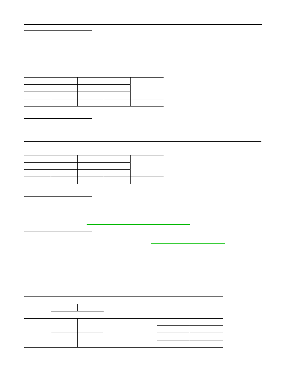
4. Check the voltage between ECM harness connector terminals as per the following condition.

Is the inspection result normal?

+

Continuity

APP sensor

ECM

Connector

Terminal

Connector

Terminal

E12

1

E16

120

Existed

+

Continuity

APP sensor

ECM

Connector

Terminal

Connector

Terminal

E12

6

E16

119

Existed

ECM

Condition

Voltage

Connector

+

Terminal

E16

126

127

Accelerator pedal

Fully released

0.6 - 0.9 V

Fully depressed

3.9 - 4.7 V

119

120

Fully released

0.3 - 0.6 V

Fully depressed

1.95 - 2.4 V

P2127, P2128 APP SENSOR

EC-437

< DTC/CIRCUIT DIAGNOSIS >

[MRA8DE]

C

D

E

F

G

H

I

J

K

L

M

A

EC

N

P

O

YES

>> INSPECTION END

NO

>> Replace accelerator pedal assembly. Refer to 

ACC-3, "Removal and Installation"

.

EC-438

< DTC/CIRCUIT DIAGNOSIS >

[MRA8DE]

P2135 TP SENSOR

P2135 TP SENSOR

DTC Logic

INFOID:0000000009758695

DTC DETECTION LOGIC

NOTE:

If DTC P2135 is displayed with DTC P0643, first perform the trouble diagnosis for DTC P0643. Refer to

EC-353, "DTC Logic"

.

DTC CONFIRMATION PROCEDURE

1.

PRECONDITIONING

If DTC Confirmation Procedure has been previously conducted, always perform the following procedure

before conducting the next test.

1. Turn ignition switch OFF and wait at least 10 seconds.

2. Turn ignition switch ON.

3. Turn ignition switch OFF and wait at least 10 seconds.

TESTING CONDITION:

Before performing the following procedure, confirm that battery voltage is more than 8 V at idle.

>> GO TO 2.

2.

PERFORM DTC CONFIRMATION PROCEDURE

1. Start engine and let it idle for 1 second.

2. Check DTC.
Is DTC detected?

YES

>> Proceed to 

EC-438, "Diagnosis Procedure"

.

NO

>> INSPECTION END

Diagnosis Procedure

INFOID:0000000009758696

1.

CHECK THROTTLE POSITION SENSOR POWER SUPPLY

1. Turn ignition switch OFF.

2. Disconnect electric throttle control actuator harness connector.

3. Turn ignition switch ON.

4. Check the voltage between electric throttle control actuator harness connector and ground.

Is the inspection result normal?

YES

>> GO TO 3.

NO

>> GO TO 2.

2.

CHECK THROTTLE POSITION SENSOR POWER SUPPLY CIRCUIT

1. Turn ignition switch OFF.

2. Disconnect ECM harness connector.

DTC No.

CONSULT screen terms

(Trouble diagnosis con-

tent)

DTC detecting condition

Possible cause

P2135

TP SENSOR-B1
(Throttle/Pedal position 
sensor/switch “A” / “B” 
voltage correlation)

Rationally incorrect voltage is sent to ECM 
compared with the signals from TP sensor 1 
and TP sensor 2.

• Harness or connector

(TP sensor 1 or 2 circuit is open or shorted.)

• Electric throttle control actuator

(TP sensor 1 or 2)

+

Voltage

(Approx.)

Electric throttle control actu-

ator

Connector

Terminal

F7

2

Ground

5.0 V

P2135 TP SENSOR

EC-439

< DTC/CIRCUIT DIAGNOSIS >

[MRA8DE]

C

D

E

F

G

H

I

J

K

L

M

A

EC

N

P

O

3. Check the continuity between electric throttle control actuator harness connector and ground.

4. Also check harness for short to ground.
Is the inspection result normal?

YES

>> Perform the trouble diagnosis for power supply circuit.

NO

>> Repair or replace error-detected parts.

3.

CHECK THROTTLE POSITION SENSOR GROUND CIRCUIT

1. Turn ignition switch OFF.

2. Disconnect ECM harness connector.

3. Check the continuity between electric throttle control actuator harness connector and ECM harness con-

nector.

4. Also check harness for short to power.
Is the inspection result normal?

YES

>> GO TO 4.

NO

>> Repair or replace error-detected parts.

4.

CHECK THROTTLE POSITION SENSOR INPUT SIGNAL CIRCUIT

1. Check the continuity between electric throttle control actuator harness connector and ECM harness con-

nector.

2. Also check harness for short to ground and to power.
Is the inspection result normal?

YES

>> GO TO 5.

NO

>> Repair open circuit or short to ground or short to power in harness or connectors.

5.

CHECK THROTTLE POSITION SENSOR

Check throttle position sensor. Refer to 

EC-439, "Component Inspection (TP Sensor)"

.

Is the inspection result normal?

YES

>> Check intermittent incident. Refer to 

GI-39, "Intermittent Incident"

.

NO

>> Replace electric throttle control actuator. Refer to 

EM-27, "Removal and Installation"

.

Component Inspection (TP Sensor)

INFOID:0000000009758697

1.

CHECK THROTTLE POSITION SENSOR

1. Turn ignition switch OFF.

+

Continuity

Electric throttle control actu-

ator

ECM

Connector

Terminal

Connector

Terminal

F7

2

F25

80

Existed

+

Continuity

Electric throttle control actu-

ator

ECM

Connector

Terminal

Connector

Terminal

F7

4

F25

78

Existed

+

Continuity

Electric throttle control actu-

ator

ECM

Connector

Terminal

Connector

Terminal

F7

1

F25

79

Existed

3

77


Content   ..  433  434  435  436   ..