Nissan Leaf. Manual - part 882
INSTRUMENT PANEL ASSEMBLY
IP-23
< REMOVAL AND INSTALLATION >
C
D
E
F
G
H
I
K
L
M
A
B
IP
N
O
P
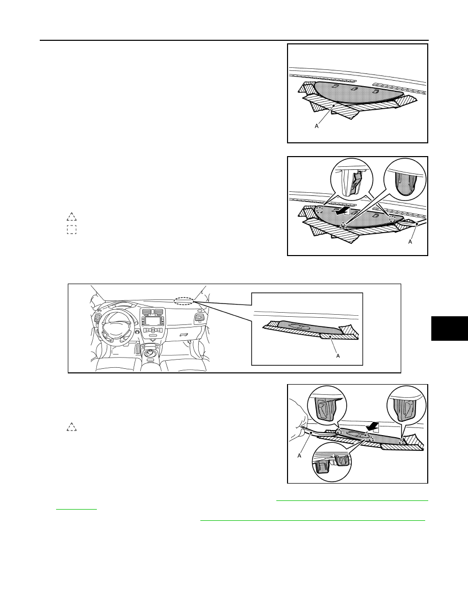
1. Apply protective tape (A) around the part to protect from
damage.
2. Insert suitable tool (A) between charging status indicator
and instrument panel assembly to disengage the pawl and
metal clips as shown.
3. Pull toward the arrow direction.
4. Disconnect harness connector.
21. Remove switch panel.
1. Apply protective tape (A) around the part to protect from damage.
2. Insert suitable tool (A) between switch panel and instrument
panel assembly to disengage the pawls as shown.
3. Pull up switch panel, then disconnect harness connectors.
22. Release front pillar portion of front body side welt RH. Refer to
INT-29, "BODY SIDE WELT : Removal and
.
23. Remove front pillar garnish RH. Refer to
INT-26, "FRONT PILLAR GARNISH : Removal and Installation"
24. Remove instrument mask RH.
JMJIA6995ZZ
: Pawl
: Metal clip
JMJIA6996ZZ
JMJIA6997ZZ
: Pawl
JMJIA6998ZZ