Nissan Leaf. Manual - part 730


  Index      Nissan     Nissan Leaf (2011-2014 year) - Service and Repair Manual


Search            


Content   ..  728  729  730  731   ..


Nissan Leaf. Manual - part 730


HA-42

< REMOVAL AND INSTALLATION >

[WITH HEAT PUMP SYSTEM]

ELECTRIC COMPRESSOR

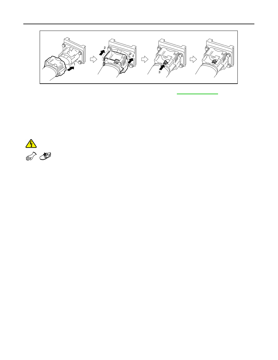
• Follow the procedure below and connect the high voltage harness connector.

• After all parts are installed, be sure to check the equipotential. Refer to 

HA-42, "Inspection"

.

Inspection

INFOID:0000000010122118

EQUIPOTENTIAL TEST

After installing the electric compressor, measure the resistance below.

• Between electric compressor (aluminum part) and body (ground bolt).

• Between electric compressor (aluminum part) and DC/DC-J/B (aluminum part).

WARNING:


To prevent electric shock hazards, be sure to wear protective gear.

If the result deviates from the standard value, check for paint, oil, dirt, or other substance adhering to the bolts

or conductive mounting parts. If such substances are found, clean the surrounding area and remove foreign

substances.

JPCIA0036ZZ

Standard

: Less than 0.1 

COOLER PIPE AND HOSE

HA-43

< REMOVAL AND INSTALLATION >

[WITH HEAT PUMP SYSTEM]

C

D

E

F

G

H

J

K

L

M

A

B

HA

N

O

P

COOLER PIPE AND HOSE

Exploded View

INFOID:0000000010122119

HIGH-PRESSURE FLEXIBLE HOSE
HIGH-PRESSURE FLEXIBLE HOSE : Removal and Installation

INFOID:0000000010122120

DANGER:

Since hybrid vehicles and electric vehicles contain a high voltage battery, there is the risk of

electric shock, electric leakage, or similar accidents if the high voltage component and vehicle are

handled incorrectly. Be sure to follow the correct work procedures when performing inspection and

maintenance.

WARNING:

• Be sure to remove the service plug in order to disconnect the high voltage circuits before perform-

ing inspection or maintenance of high voltage system harnesses and parts.

• The removed service plug must always be carried in a pocket of the responsible worker or placed in

the tool box during the procedure to prevent the plug from being connected by mistake.

• Be sure to wear insulating protective equipment consisting of glove, shoes, face shield and glasses

before beginning work on the high voltage system.

1.

2-way and 3-way valve assembly

2.

O-ring

3.

O-ring

4.

Accumulator assembly

5.

Condenser

6.

Low-pressure flexible hose

7.

Electric compressor

8.

High-pressure flexible hose

9.

High-pressure pipe

10. Heating and cooling unit assembly

 : Always replace after every disassembly.

 : N·m (kg-m, in-lb)

JMIIA2635GB

HA-44

< REMOVAL AND INSTALLATION >

[WITH HEAT PUMP SYSTEM]

COOLER PIPE AND HOSE

• Never allow workers other than the responsible person to touch the vehicle containing high voltage

parts. To keep others from touching the high voltage parts, these parts must be covered with an insu-

lating sheet except when using them. Refer to 

GI-34, "High Voltage Precautions"

.

CAUTION:

Never bring the vehicle into the READY status with the service plug removed unless otherwise

instructed in the Service Manual. A malfunction may occur if this is not observed.

REMOVAL

1. Use the refrigerant recovery equipment (for HFC134a) and recover the refrigerant. Refer to 

HA-27, "Recy-

cle Refrigerant"

.

2. Remove radiator upper grille. Refer to

DLK-165, "RADIATOR UPPER GRILLE : Removal and Installation"

.

3. Remove washer tank inlet. Refer to 

WW-43, "Exploded View"

.

4. Remove bolts (A), and then disconnect high-pressure flexible hose (1) from high pressure pipe (2).

CAUTION:

To prevent the inclusion of foreign matter, use a cap or vinyl tape to seal off the connection ports

of the pipe and condenser from the atmosphere.

5. Remove bolts (A), and then disconnect high-pressure flexible hose from electric compressor.

WARNING:


To prevent electric shock hazards, be sure to wear protective gear.

CAUTION:

To prevent the inclusion of foreign matter, use a cap or vinyl tape to seal off the connection ports

of the pipe and electric compressor from the atmosphere.

6. Disconnect high-pressure flexible hose from the vehicle.

INSTALLATION

Note the following items, and then install in the reverse order of removal.

CAUTION:

• To prevent degradation in insulation performance, use special electric compressor oil as the com-

pressor oil.

• In order to prevent conventional PAG oil from becoming mixed in, never reuse recovered compres-

sor oil and instead always use new oil. The use of oil including the conventional PAG oil may

degrade the performance of insulation.

• To prevent performance degradation, never use a fluorescent agent in order to detect refrigerant

leakage. Also be careful that a fluorescent agent never enter the oil.

JMIIA2654ZZ

JMIIA2645ZZ

COOLER PIPE AND HOSE

HA-45

< REMOVAL AND INSTALLATION >

[WITH HEAT PUMP SYSTEM]

C

D

E

F

G

H

J

K

L

M

A

B

HA

N

O

P

• To prevent leakage of refrigerant, replace the O-ring with a new one. Apply a coat of compressor oil

to the O-ring prior to installation.

• Perform a check for refrigerant leakage when charging with refrigerant. Refer to 

HA-26, "Check

Refrigerant Leakage"

.

LOW-PRESSURE FLEXIBLE HOSE
LOW-PRESSURE FLEXIBLE HOSE : Removal and Installation

INFOID:0000000010122121

DANGER:

Since hybrid vehicles and electric vehicles contain a high voltage battery, there is the risk of

electric shock, electric leakage, or similar accidents if the high voltage component and vehicle are

handled incorrectly. Be sure to follow the correct work procedures when performing inspection and

maintenance.

WARNING:

• Be sure to remove the service plug in order to disconnect the high voltage circuits before perform-

ing inspection or maintenance of high voltage system harnesses and parts.

• The removed service plug must always be carried in a pocket of the responsible worker or placed in

the tool box during the procedure to prevent the plug from being connected by mistake.

• Be sure to wear insulating protective equipment consisting of glove, shoes, face shield and glasses

before beginning work on the high voltage system.

• Never allow workers other than the responsible person to touch the vehicle containing high voltage

parts. To keep others from touching the high voltage parts, these parts must be covered with an insu-

lating sheet except when using them. Refer to 

GI-34, "High Voltage Precautions"

.

CAUTION:

Never bring the vehicle into the READY status with the service plug removed unless otherwise

instructed in the Service Manual. A malfunction may occur if this is not observed.

REMOVAL

1. Use the refrigerant recovery equipment (for HFC134a) and recover the refrigerant. Refer to 

HA-27, "Recy-

cle Refrigerant"

.

2. Remove cowl top extension. Refer to 

EXT-19, "Removal and Installation"

.

3. Remove radiator upper grille. Refer to 

DLK-165, "RADIATOR UPPER GRILLE : Removal and Installa-

tion"

.

4. Remove bolt (A), and then disconnect low-pressure flexible hose (1) from accumulator assembly (2).

CAUTION:

To prevent the inclusion of foreign matter, use a cap or vinyl tape to seal off the connection ports

of the pipe and expansion valve from the atmosphere.

5. Remove bolt (A), and then disconnect low-pressure flexible hose from electric compressor.

JMIIA2655ZZ

JMIIA2646ZZ


Content   ..  728  729  730  731   ..