Nissan Leaf. Manual - part 596


  Index      Nissan     Nissan Leaf (2011-2014 year) - Service and Repair Manual


Search            


Content   ..  594  595  596  597   ..


Nissan Leaf. Manual - part 596


EVC-408

< DTC/CIRCUIT DIAGNOSIS >

CHARGE PORT LAMP

Is the inspection result normal?

YES

>> Check intermittent incident. Refer to 

GI-53, "Intermittent Incident"

.

NO

>> Repair or replace error-detected parts.
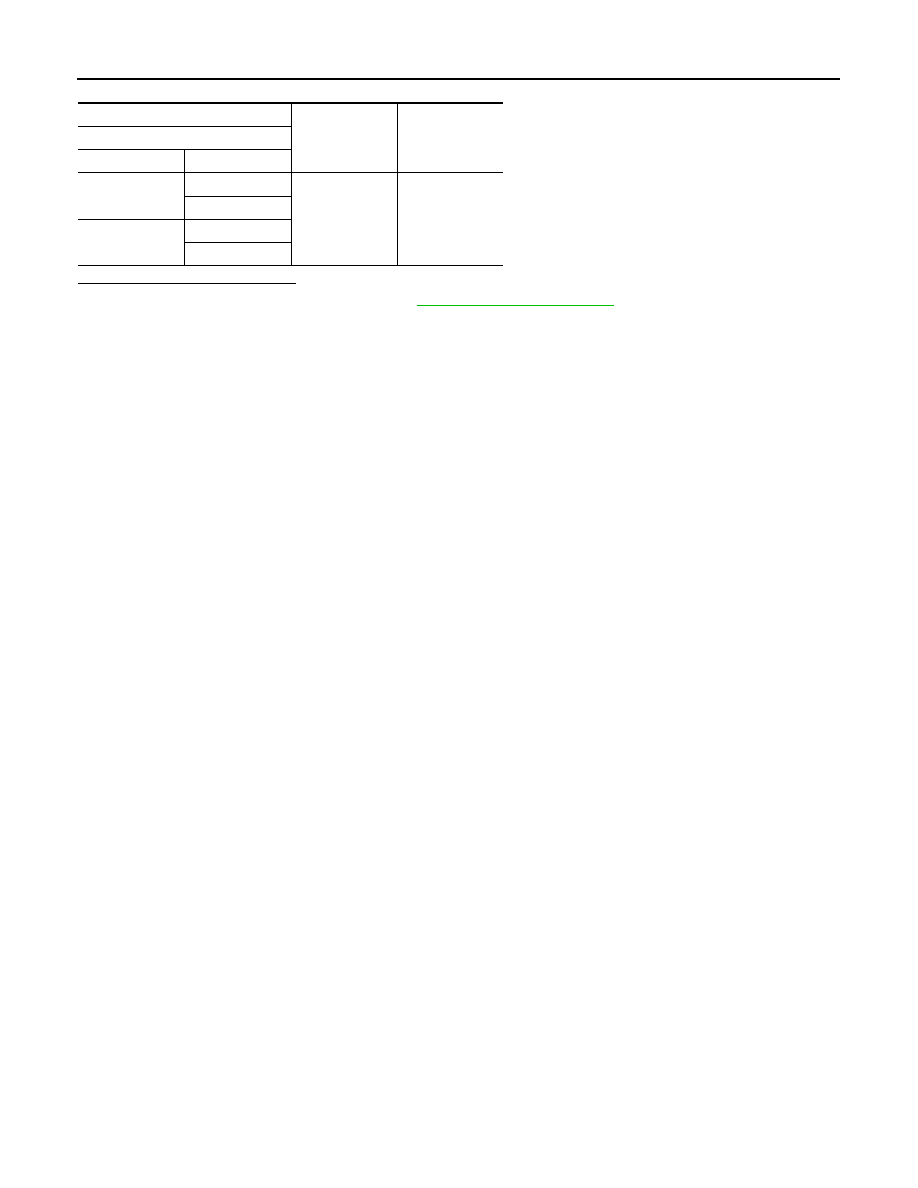
+

Continuity

VCM

Connector

Terminal

E61

58

Ground

Existed

65

E62

118

126

EV CONTROL SYSTEM

EVC-409

< SYMPTOM DIAGNOSIS >

D

E

F

G

H

I

J

K

L

M

A

B

EVC

N

O

P

SYMPTOM DIAGNOSIS

EV CONTROL SYSTEM

Symptom Index

INFOID:0000000010120860

NOTE:

• Perform self-diagnoses with CONSULT before performing the symptom diagnosis.

• If any DTC is detected, perform the corresponding diagnosis.

Symptom

Reference page

READY status cannot be achieved.

EVC-410, "READY Status Cannot Be Achieved"

Unable to travel.

EVC-411, "Unable to Travel"

Low electrical consumption

EVC-412, "Low Electrical Consumption"

Power switch does not turn OFF.

EVC-413, "Power Switch Does Not Turn OFF"

No regeneration

EVC-414, "No Regeneration"

Decelerating force changes

EVC-415, "Decelerating Force Changes"

Normal charge does not start.

EVC-416, "Normal Charge Does Not Start"

Timer charge and remote charge does not start.

EVC-417, "Timer Charge and Remote Charge Does Not Start"

Immediate charge does not start.

EVC-418, "Immediate Charge Does Not Start"

Normal charge is not completed.

EVC-418, "Normal Charge Is Not Completed"

Quick charge does not start.

EVC-419, "Quick Charge Does Not Start"

Quick charge is not completed.

EVC-419, "Quick Charge Is Not Completed"

Full charge cannot be achieved.

EVC-420, "Full Charge Cannot Be Achieved"

Climate Ctrl. Timer does not start.

EVC-420, "Climate Ctrl. Timer Does Not Start"

Remote climate control does not start.

EVC-421, "Remote climate control Does Not Start"

EVC-410

< SYMPTOM DIAGNOSIS >

EV CONTROL SYSTEM

READY Status Cannot Be Achieved

INFOID:0000000010120861

Symptom

Possible cause

Action

READY st

at

us

 ca

nn

ot

 be

 a

ch

iev

ed

.

READY condition are not 
satisfied

BCM does not output a 
READY signal.

Abnormal stop lamp switch.

EVC-208, "Component Function 
Check"

Abnormal stop lamp switch 
signal line.

Check the signal line between stop 
lamp switch and BCM.

Abnormal power switch

PCS-64, 
"Component Function Check"

Abnormal power switch sig-
nal line.

Check the signal line between BCM 
and VCM.

A READY signal is not input 
to VCM.

Abnormal READY signal 
line

Check the signal line between BCM 
and VCM.

VCM recognizes that the se-
lector lever is in a range oth-
er than P and N.

Electric shift control system 
error.

Perform self-diagnosis of Electric 
shift control module.

VCM recognizes that the 
charge connector is con-
nected.

• Abnormal normal charge 

connector connection de-
tection circuit.

• Abnormal quick charge 

connector connection de-
tection circuit.

Perform self-diagnosis of PDM 
(Power Delivery Module).

Fail-safe of VCM prohibits 
READY.

EV control system error.

Perform self-diagnosis of VCM.

VCM recognizes that Li-ion 
battery remaining energy is 
low.

Li-ion battery remaining en-
ergy is low.

Charge Li-ion battery.

Abnormal LBC.

Perform self-diagnosis of LBC.

VCM recognizes that steer-
ing lock is not released.

Abnormal steering lock 
mechanism.

Check steering lock system.

The READY to drive indicator lamp does not turn ON de-
spite READY state.

• Abnormal combination 

meter.

• Abnormal LED.
• Abnormal VCM.

Perform ACTIVE TEST of VCM to 
check the READY to drive indicator 
lamp. Refer to 

EVC-72, "CONSULT 

Function"

.

EV CONTROL SYSTEM

EVC-411

< SYMPTOM DIAGNOSIS >

D

E

F

G

H

I

J

K

L

M

A

B

EVC

N

O

P

Unable to Travel

INFOID:0000000010120862

Symptom

Possible cause

Action

Un

abl

e to trav

el

.

Drive force is not generated.

VCM recognizes that the ac-
celerator pedal is not de-
pressed.

Abnormal accelerator pedal 
position sensor.

EVC-211, "Diagnosis Procedure"

VCM recognizes that brake 
pedal is depressed.

• Abnormal stop lamp 

switch.

• Abnormal stop lamp 

switch signal line.

EVC-201, "Diagnosis Procedure"

An output limit request sig-
nal of TCS/VDC/ABS is re-
ceiced.

TCS/VDC/ABS system er-
ror.

Perform self-diagnosis of ABS actu-
ator and electric unit (control unit).

Traction motor inverter re-
quests the output limit.

Traction motor system error.

Check the “POWER LIMIT CAUSE” 
in DATA MONITOR item of VCM.

LBC requests the output 
limit.

LBC system error.

Fail-safe of VCM prohibits 
READY.

EV control system error.

Perform self-diagnosis of VCM.

Motor output is not con-
veyed to drive wheels.

Abnormal reduction gear.

Check reduction gear.

Braking force is generated.

Brake applied.

Brake dragging.

Check for brake dragging.

A brake signal is input to 
ABS actuator and electric 
unit (control unit). 

Abnormal stop lamp switch 
signal line.

Check the signal line between stop 
lamp switch and ABS actuator and 
electric unit (control unit).

Parking lock is ON.

• Abnormal electric shift 

control module.

• Abnormal parking actua-

tor.

Perform self-diagnosis of Electric 
shift control module.


Content   ..  594  595  596  597   ..