Nissan Leaf. Manual - part 585


  Index      Nissan     Nissan Leaf (2011-2014 year) - Service and Repair Manual


Search            


Content   ..  583  584  585  586   ..


Nissan Leaf. Manual - part 585


EVC-364

< DTC/CIRCUIT DIAGNOSIS >

P31EE REFRIGERANT PRESSURE SENSOR

Check intermittent incident. Refer to 

GI-53, "Intermittent Incident"

.

Is the inspection result normal?

YES

>> Replace VCM. Refer to 

EVC-423, "Removal and Installation"

.

NO

>> Repair or replace error-detected parts.

7.

CHECK REFRIGERANT PRESSURE SENSOR SIGNAL CIRCUIT

1. Turn power switch OFF.

2. Disconnect VCM harness connector.

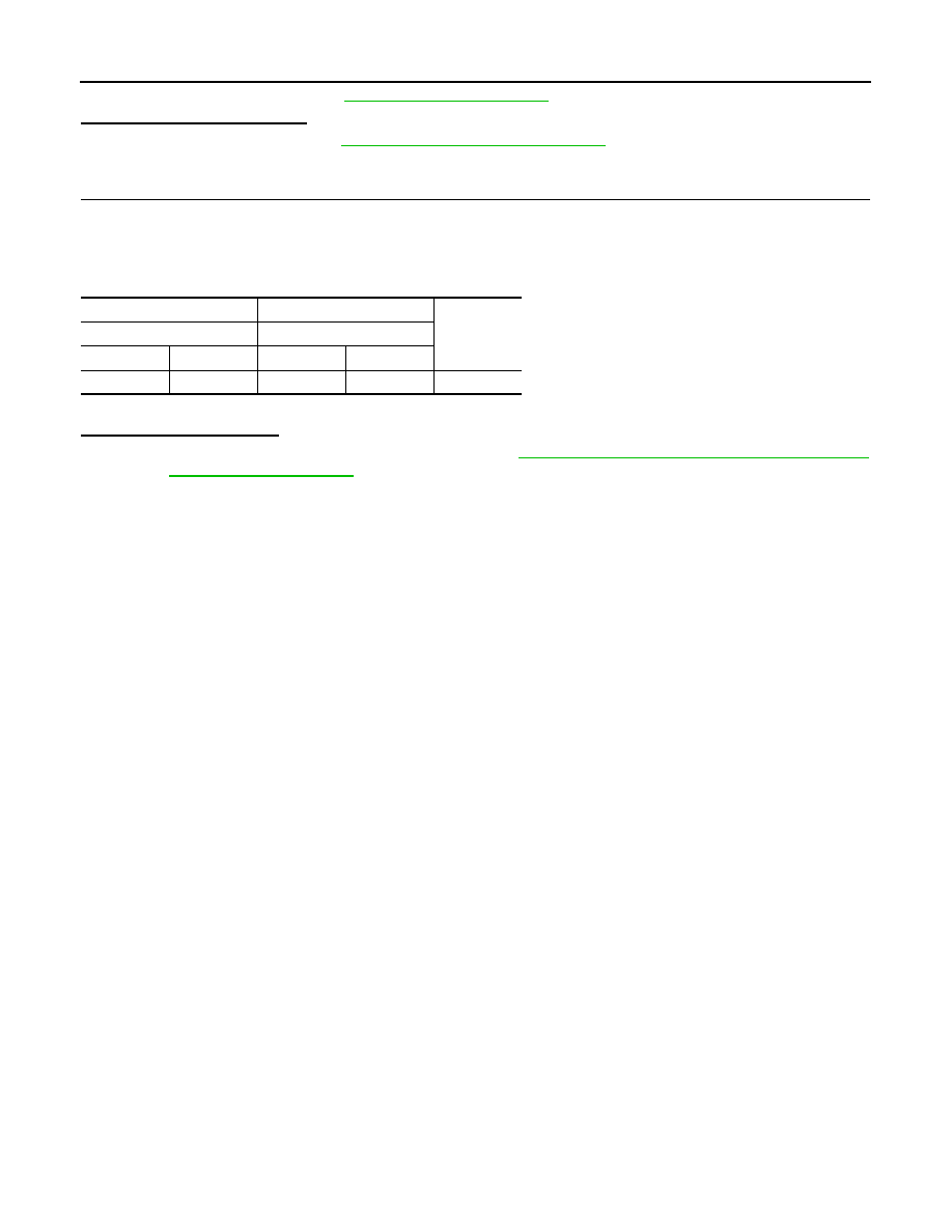
3. Check the continuity between refrigerant pressure sensor harness connector and VCM harness connec-

tor.

4. Also check harness for short to power and short to ground.
Is the DTC detected again?

YES

>> Replace refrigerant pressure sensor. Refer to 

HA-43, "HIGH-PRESSURE FLEXIBLE HOSE :

Removal and Installation"

.

NO

>> Repair or replace error-detected parts.

+

Continuity

Refrigerant pressure sensor

VCM

Connector

Terminal

Connector

Terminal

E49

3

E62

98

Existed

P31F2 AV INFORMATION MISMATCH

EVC-365

< DTC/CIRCUIT DIAGNOSIS >

D

E

F

G

H

I

J

K

L

M

A

B

EVC

N

O

P

P31F2 AV INFORMATION MISMATCH

DTC Logic

INFOID:0000000010120826

DTC DETECTION LOGIC

DTC CONFIRMATION PROCEDURE

1.

PRECONDITIONING

• Turn power switch OFF and wait at least 90 seconds.

CAUTION:

During this period, never perform vehicle handling such as opening and closing of doors. If some

kind of vehicle handling is performed, then wait another 90 seconds or more from the time of the

vehicle handling.

• Make sure that 12V battery voltage is 11 V or more.

>> GO TO 2.

2.

PERFORM DTC CONFIRMATION PROCEDURE-1

With CONSULT

1. Turn power switch OFF and wait at least 90 seconds.

CAUTION:

During this period, never perform vehicle handling such as opening and closing of doors. If some

kind of vehicle handling is performed, then wait another 90 seconds or more from the time of the

vehicle handling.

2. Turn power switch ON.

3. Change the timer charge setting 1 on navigation display and wait at least 10 seconds.

4. Check DTC.
Is DTC detected?

YES

>> Proceed to 

EVC-366, "Diagnosis Procedure"

.

NO

>> GO TO 3.

3.

PERFORM DTC CONFIRMATION PROCEDURE-2

With CONSULT

1. Turn power switch OFF and wait at least 90 seconds.

CAUTION:

During this period, never perform vehicle handling such as opening and closing of doors. If some

kind of vehicle handling is performed, then wait another 90 seconds or more from the time of the

vehicle handling.

2. Turn power switch ON.

3. Change the timer charge setting 2 on navigation display and wait at least 10 seconds.

4. Check DTC.
Is DTC detected?

YES

>> Proceed to 

EVC-366, "Diagnosis Procedure"

.

NO

>> GO TO 4.

4.

PERFORM DTC CONFIRMATION PROCEDURE-3

With CONSULT

1. Turn power switch OFF and wait at least 90 seconds.

CAUTION:

During this period, never perform vehicle handling such as opening and closing of doors. If some

kind of vehicle handling is performed, then wait another 90 seconds or more from the time of the

vehicle handling.

2. Turn power switch ON.

DTC

CONSULT screen terms

(Trouble diagnosis content)

DTC detecting condition

Possible cause

P31F2

AV SET INFORMATION
(AV set information)

Setting of timer charge does not succeed for 5 seconds after 
VCM receives a timer charge set signal.

• AV  control  unit
• VCM

EVC-366

< DTC/CIRCUIT DIAGNOSIS >

P31F2 AV INFORMATION MISMATCH

3. Change the Climate Ctrl. Timer setting 1 on navigation display and wait at least 10 seconds.

4. Check DTC.
Is DTC detected?

YES

>> Proceed to 

EVC-366, "Diagnosis Procedure"

.

NO

>> GO TO 5.

5.

PERFORM DTC CONFIRMATION PROCEDURE-4

1. Turn power switch OFF and wait at least 90 seconds.

CAUTION:

During this period, never perform vehicle handling such as opening and closing of doors. If some

kind of vehicle handling is performed, then wait another 90 seconds or more from the time of the

vehicle handling.

2. Turn power switch ON.

3. Change the Climate Ctrl. Timer setting 2 on navigation display and wait at least 10 seconds.

4. Check DTC.
Is DTC detected?

YES

>> Proceed to 

EVC-366, "Diagnosis Procedure"

.

NO

>> INSPECTION END

Diagnosis Procedure

INFOID:0000000010120827

1.

REPLACE AV CONTROL UNIT

1. Replace AV control unit. Refer to 

AV-318, "Removal and Installation"

.

2. Erase DTC.

3. Perform DTC confirmation procedure again. Refer to 

EVC-365, "DTC Logic"

.

Is the DTC detected again?

YES

>> Replace VCM. Refer to 

EVC-423, "Removal and Installation"

.

NO

>> INSPECTION END

COOLING FAN

EVC-367

< DTC/CIRCUIT DIAGNOSIS >

D

E

F

G

H

I

J

K

L

M

A

B

EVC

N

O

P

COOLING FAN

Component Function Check

INFOID:0000000010120828

1.

CHECK COOLING FAN FUNCTION

 WITH CONSULT

1. Turn power switch ON.

2. Perform “COOLING FAN” in “ACTIVE TEST” mode with CONSULT.

3. Check that cooling fan speed varies according to the percentage.
Is the inspection result normal?

YES

>> INSPECTION END

NO

>> Proceed to 

EVC-367, "Diagnosis Procedure"

.

Diagnosis Procedure

INFOID:0000000010120829

1.

CHECK COOLING FAN CONTROL MODULE POWER SUPPLY

1. Turn power switch OFF.

2. Disconnect cooling fan control module harness connector.

3. Turn power switch ON.

4. Check the voltage between cooling fan control module harness connector and ground.

Is the inspection result normal?

YES

>> GO TO 11.

NO

>> GO TO 2.

2.

CHECK 12V BATTERY POWER SUPPLY

1. Turn power switch OFF.

2. Remove cooling fan relay.

3. Check the voltage between cooling fan relay harness connector and ground.

Is the inspection result normal?

YES

>> GO TO 3.

NO

>> Check power supply circuit for 12V battery power supply.

3.

CHECK COOLING FAN RELAY OUTPUT VOLTAGE-1

1. Turn power switch ON.

2. Check the voltage between cooling fan relay harness connector and ground.

+

Voltage

Cooling fan control module

Connector

Terminal

E19

3

Ground

12V battery volt-

age

+

Voltage

Cooling fan relay

Connector

Terminal

E18

3

Ground

12V battery volt-

age

+

Voltage

Cooling fan relay

Connector

Terminal

E18

1

Ground

12V battery volt-

age


Content   ..  583  584  585  586   ..