Nissan Leaf. Manual - part 531


  Index      Nissan     Nissan Leaf (2011-2014 year) - Service and Repair Manual


Search            


Content   ..  529  530  531  532   ..


Nissan Leaf. Manual - part 531


EVC-148

< DTC/CIRCUIT DIAGNOSIS >

P0A0B HIGH VOLTAGE CONNECTOR INTERLOCK DETECT CIRCUIT

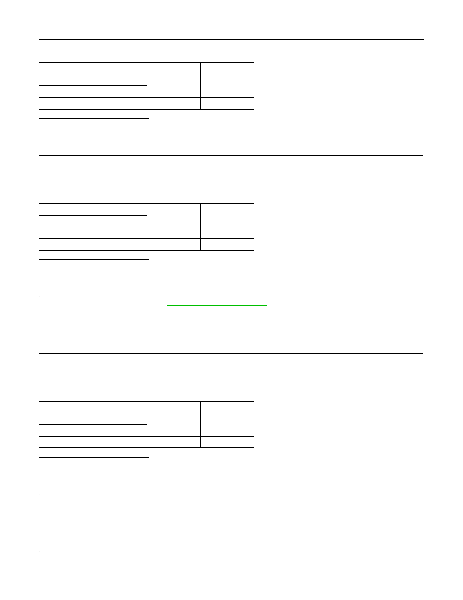
4. Check the voltage between PDM (Power Delivery Module) harness connector and ground.

Is the inspection result normal?

YES

>> GO TO 6.

NO

>> GO TO 4.

4.

CHECK CONNECTION DETECTING CIRCUIT POWER SUPPLY CIRCUIT

1. Turn power switch OFF.

2. Disconnect VCM harness connector.

3. Check the harness for short to power, between PDM (Power Delivery Module) harness connector and

VCM harness connector.

Is the inspection result normal?

YES

>> GO TO 5.

NO

>> Repair or replace error-detected parts.

5.

CHECK INTERMITTENT INCIDENT

Check intermittent incident. Refer to 

GI-53, "Intermittent Incident"

.

Inspection result normal?

YES

>> Replace VCM. Refer to 

EVC-423, "Removal and Installation"

.

NO

>> Repair or replace error-detected parts.

6.

CHECK CONNECTION DETECTING CIRCUIT SIGNAL CIRCUIT

1. Turn power switch OFF.

2. Disconnect VCM harness connector.

3. Check the harness for short to power, between PDM (Power Delivery Module) harness connector and

VCM harness connector.

Is the inspection result normal?

YES

>> GO TO 7.

NO

>> Repair or replace error-detected parts.

7.

CHECK INTERMITTENT INCIDENT

Check intermittent incident. Refer to 

GI-53, "Intermittent Incident"

.

Inspection result normal?

YES

>> GO TO 8.

NO

>> Repair or replace error-detected parts.

8.

REPLACE VCM

1. Replace VCM. Refer to 

EVC-423, "Removal and Installation"

.

2. Reconnect harness connector and parts disconnected.

3. Perform DTC Confirmation Procedure. Refer to 

EVC-146, "DTC Logic"

.

+

Voltage

PDM (Power Delivery Module)

Connector

Terminal

F23

12

Ground

3 – 7 V

+

Voltage

PDM (Power Delivery Module)

Connector

Terminal

F23

12

Ground

0 V

+

Voltage

PDM (Power Delivery Module)

Connector

Terminal

F23

15

Ground

0 V

P0A0B HIGH VOLTAGE CONNECTOR INTERLOCK DETECT CIRCUIT

EVC-149

< DTC/CIRCUIT DIAGNOSIS >

D

E

F

G

H

I

J

K

L

M

A

B

EVC

N

O

P

Is DTC P0A0B detected again?

YES

>> Replace PDM (Power Delivery Module). Refer to 

VC-112, "Removal and Installation"

.

NO

>> INSPECTION END

EVC-150

< DTC/CIRCUIT DIAGNOSIS >

P0A8D 12V BATTERY POWER SUPPLY

P0A8D 12V BATTERY POWER SUPPLY

DTC Logic

INFOID:0000000010120615

DTC DETECTION LOGIC

DTC CONFIRMATION PROCEDURE

1.

PRECONDITIONING

• Turn power switch OFF and wait at least 90 seconds.

CAUTION:

During this period, never perform vehicle handling such as opening and closing of doors. If some

kind of vehicle handling is performed, then wait another 90 seconds or more from the time of the

vehicle handling.

• Make sure that 12V battery voltage is 11 V or more.

>> GO TO 2.

2.

PERFORM DTC CONFIRMATION PROCEDURE

With CONSULT

1. Set the vehicle to READY and wait at least 30 seconds.

2. Check self-diagnostic result.
Is DTC detected?

YES

>> Proceed to 

EVC-150, "Diagnosis Procedure"

.

NO

>> INSPECTION END

Diagnosis Procedure

INFOID:0000000010120616

1.

CHECK SELF-DIAGNOSTIC RESULT IN PDM (POWER DELIVERY MODULE)

With CONSULT

Check self-diagnostic result in “CHARGER/PD MODULE”.
Is any DTC detected?

YES

>> Perform trouble diagnosis for detected DTC. Refer to 

VC-34, "DTC Index"

.

NO

>> GO TO 2.

2.

CHECK SELF-DIAGNOSTIC RESULT IN VCM

With CONSULT

Check self-diagnostic result in “EV/HEV”.
Is DTC (excluding P0A8D) related to DC/DC converter detected?

YES

>> Perform trouble diagnosis for detected DTC. Refer to 

EVC-102, "DTC Index"

.

NO

>> GO TO 3.

3.

CHECK 12V BATTERY POWER SUPPLY

1. Turn power switch OFF.

2. Check the voltage between IPDM E/R harness connector and ground.

DTC

CONSULT screen terms

(Trouble diagnosis content)

DTC detecting condition

Possible cause

P0A8D

14V POWER SUPPLY
(14 V power module system 
voltage low)

VCM detects that a voltage of 12V battery power sup-
ply remains less than 10 V for 10 seconds during 
READY state.

• Harness or connectors

(The sensor circuit is open or 
shorted.)

• DC/DC converter
• IPDM  E/R

P0A8D 12V BATTERY POWER SUPPLY

EVC-151

< DTC/CIRCUIT DIAGNOSIS >

D

E

F

G

H

I

J

K

L

M

A

B

EVC

N

O

P

Is the inspection result normal?

YES

>> GO TO 6.

NO

>> GO TO 4.

4.

CHECK FUSE

1. Pull out #43 fuse.

2. Check the fuse is not fusing.
Is the inspection result normal?

YES

>> GO TO 5.

NO

>> Replace the fuse after replacing the applicable circuit.

5.

CHECK IPDM E/R

1. Insert the fuse which pulled out.

2. Remove IPDM E/R. Refer to 

PCS-29, "Removal and Installation"

.

3. Check the continuity between IPDM E/R connector terminals.

Is the inspection result normal?

YES

>> GO TO 6.

NO

>> Replace IPDM E/R. Refer to 

PCS-29, "Removal and Installation"

.

6.

CHECK 12V BATTERY POWER SUPPLY CIRCUIT

1. Disconnect VCM harness connector.

2. Check the continuity between IPDM E/R harness connector and VCM harness connector.

3. Also check harness for short to ground.
Is the inspection result normal?

YES

>> Check intermittent incident. Refer to 

GI-53, "Intermittent Incident"

.

NO

>> Repair or replace error-detected parts.

+

Voltage

IPDM E/R

Connector

Terminal

E14

42

Ground

12V battery volt-

age

IPDM E/R

Continuity

+

Terminal

2

42

Existed

+

Continuity

IPDM E/R

VCM

Connector

Terminal

Connector

Terminal

E14

42

E61

11

Existed


Content   ..  529  530  531  532   ..